

Tutorial: Your First State Machine
Step by step: build a two-state machine that switches an LED on and off with a button, using the project tree button, the transition graph, State Ports and EXIT CONDITION blocks, then place it in the top design.
Goal
A machine fsm_led with two states:
IDLE(initial): LED off; go toONwhen the inputBTNis 1;ON: LED on; go back toIDLEwhenBTNis 1.
This is the same logic as the Toggle example, built by hand. Note that while BTN is held at 1 the machine changes state on every clock: in a real design feed BTN with a one-clock pulse (for example the PULSE output of the Button debouncer example).
Step 1 - Create the machine
Click New State Machine in the toolbar of the Project panel, type fsm_led and
press OK.
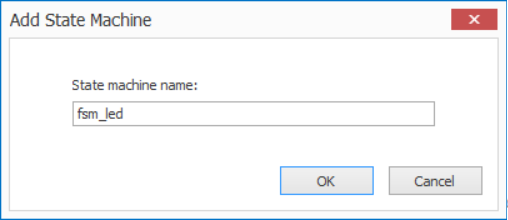
Figure 1: naming the machine
The machine appears in the tree under Unused with one state, IDLE. Double-click the
fsm_led node to open the editor. IDLE is the initial state (▶ INIT) and is
terminal because it has no transitions yet.
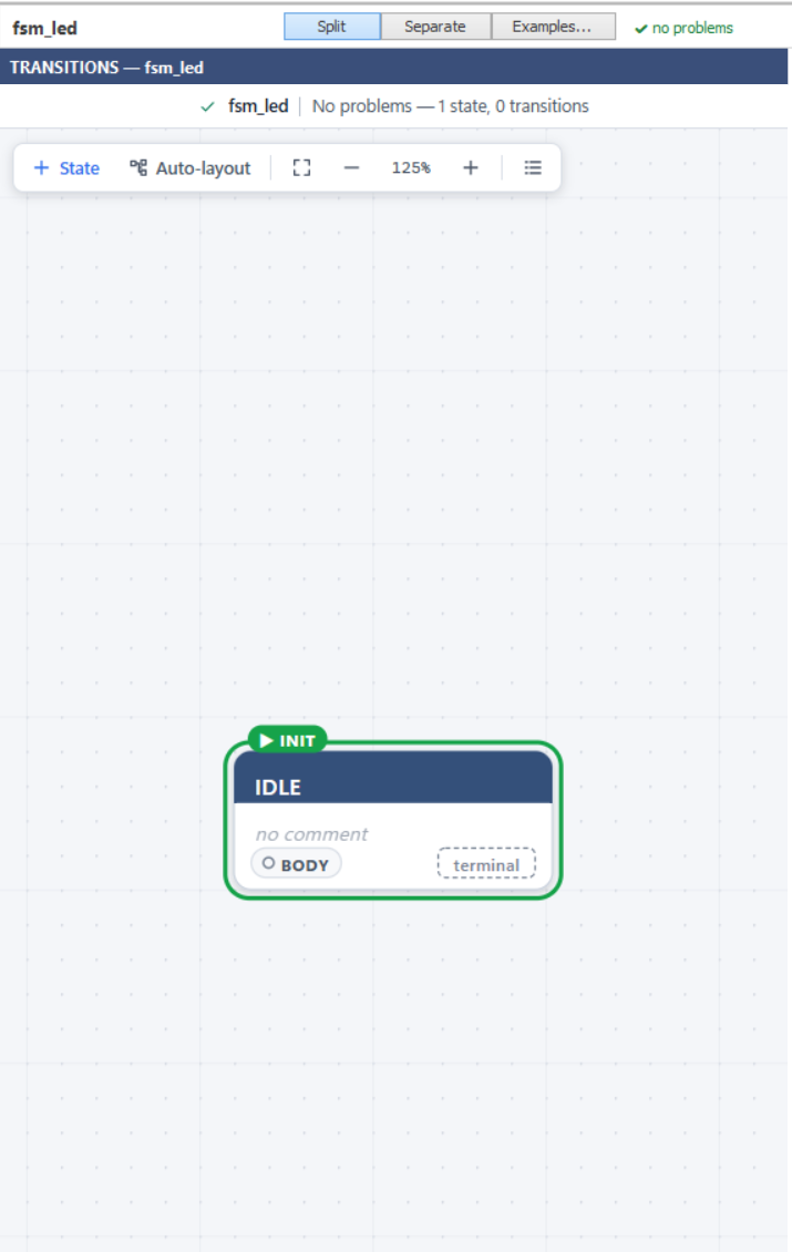
Figure 2: a new machine: one state, IDLE
Step 2 - Add the second state
Click + State in the graph toolbar (or double-click the empty canvas), type ON
and press OK. Use Fit to view (F) if the new card is out of sight, and drag the
cards where you like.
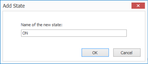
Figure 3: naming the new state
Step 3 - Draw the transitions
Hover IDLE: a small ● handle appears on the right edge of the card. Drag it onto
ON. Do the same from ON back to IDLE. The two transitions get the default names
IDLE_ON and ON_IDLE, priority 1.
They are red and dashed and the cards show 0/1 exits: each transition still needs its EXIT CONDITION block. The header lists the two problems.
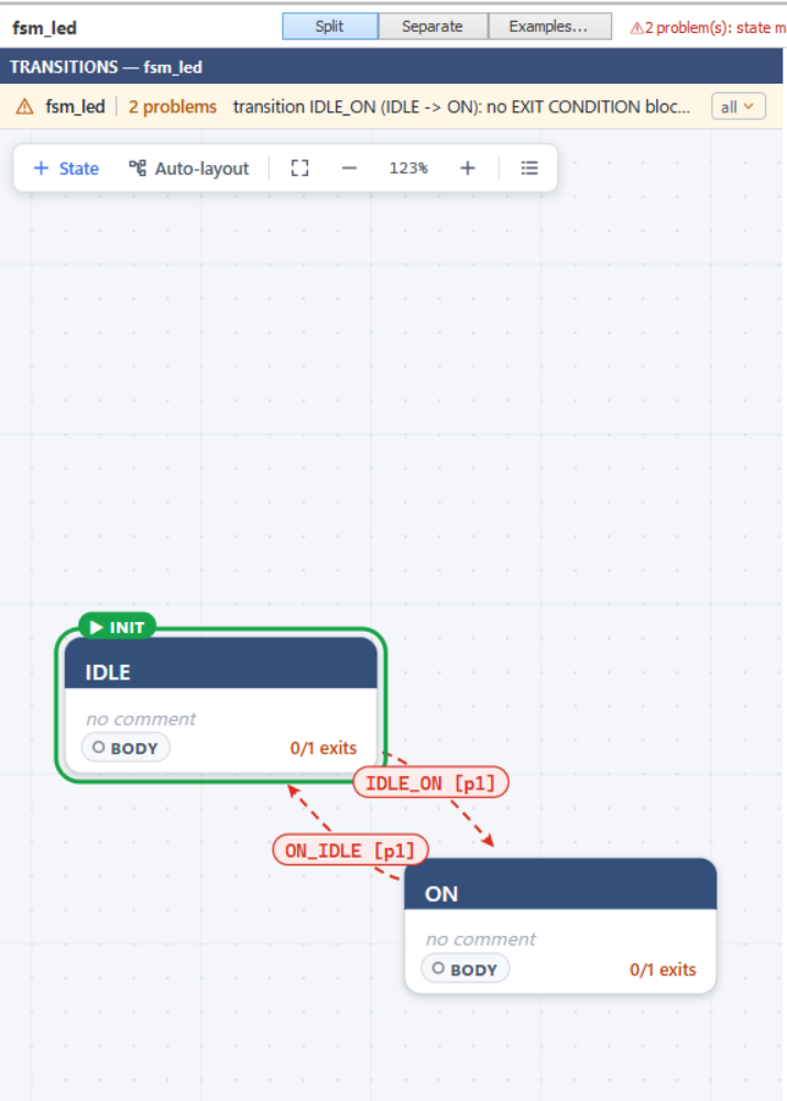
Figure 4: transitions drawn, exit conditions missing
Step 4 - Body of IDLE: input port and exit condition
-
Click the IDLE card: its body opens on the right (BODY — IDLE).
-
In the Blocks panel search “State Port” and double-click State Port (IN). The machine has no ports yet, so three short dialogs ask the name (
BTN), the signal type (std_logic_vector) and the width (1). Click on the canvas to drop the block.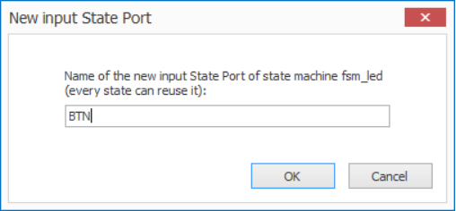
Figure 5: declaring the input port BTN
-
Click + Exit Condition in the body caption; the chooser proposes
IDLE_ON; press OK. Move theEXIT ► IDLE_ONblock next to BTN (click its caption, then drag it). -
Drag a wire from the BTN pin to the input of
EXIT ► IDLE_ON.
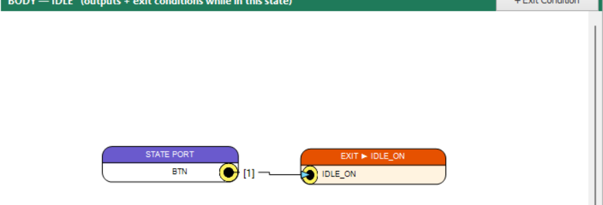
Figure 6: body of IDLE: the machine goes to ON when BTN = 1
Step 5 - Body of ON: reuse the port, add the LED output
-
Click the ON card.
-
Double-click State Port (IN) again: this time the chooser lists the port already declared, BTN [in, 1 bit]. Pick it: the same machine input is reused in this state.
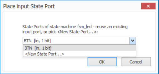
Figure 7: reusing BTN in the second state
-
+ Exit Condition →
ON_IDLE, then wire BTN to it, as in step 4. -
Place a True/False constant (search “Bit Constant” or “True/False”, keep the value True).
-
Right-click its output pin and choose Connect to new State Port; name it
LED. An output State Port is placed next to the pin and wired. In IDLE nothing drives LED, so LED is 0 there.
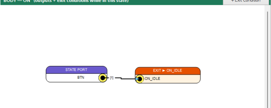
Figure 8: body of ON: LED = 1, back to IDLE when BTN = 1
The header now shows no problems and both cards show 1/1 exits.
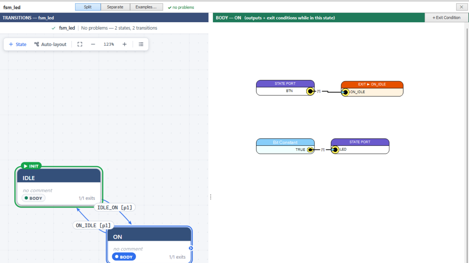
Figure 9: the finished machine
Step 6 - Place the machine in the design
- Open the top page (double-click it in the tree).
- Search State Machine (new) in the Blocks panel and double-click it, select
fsm_ledand press OK. - Connect
BTNandLED(for example to a debounced button and to a digital output);CLKandRESETmay stay unconnected (default clock and reset).STATE_OUTandTRANSITION_OUTare optional.
Double-click the placed block whenever you want to edit the machine again. Save the
project and compile it as usual: the compiler generates FSM_fsm_led and one body
entity per state (see Generated HDL).
Going Further
- Start from a gallery example instead of an empty machine: State Machine Examples.
- Time a state with a Timer and STATE ENTERED, or keep a value between states with a State Variable: State Bodies, Ports and Variables.