
Digitizer
Multi-channel waveform digitizer with event-driven acquisition. Captures waveforms with timestamp, hit pattern, and user data for list-mode readout.
Introduction
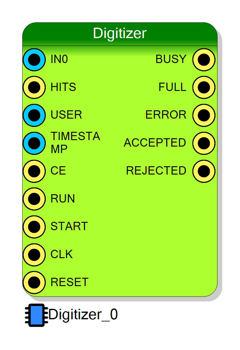
The Digitizer block performs multi-channel waveform digitization with event-driven acquisition. When triggered by the START signal, it captures waveforms from all enabled channels along with timestamp, hit pattern, and user-defined data.
The digitized data is transferred to the host PC in list mode format, allowing continuous acquisition of triggered events.
The data can be read via Resource Explorer or programmatically using the SciSDK library.
SciSDK Documentation: https://nuclearinstruments.github.io/SCISDK/
Pin Description
64-bit general purpose register for hit pattern information. Typically used to store which channels triggered the event.
Captured on the rising edge of START.
32-bit general purpose register for user-defined data. Can store any additional event information.
Captured on the rising edge of START.
64-bit timestamp input. Connect to the board or system timestamp generator for event timing.
Captured on the rising edge of START.
Clock Enable for sample storage. When HIGH, samples are stored on each clock cycle during acquisition.
Use this to implement decimation or conditional sampling.
Acquisition trigger input.
- Rising edge: Latches TIMESTAMP, HITS, USER and begins waveform capture
- HIGH: Samples are captured each clock (if CE is HIGH)
- Falling edge: Ends acquisition and transfers data to FIFO
Ignored while BUSY is HIGH or RUN is LOW.
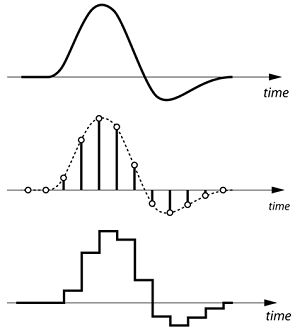
Waveform data inputs, one for each channel. 16-bit signed input representing the analog signal to digitize.
Samples are captured on each clock cycle while START is HIGH and CE is HIGH.
Properties
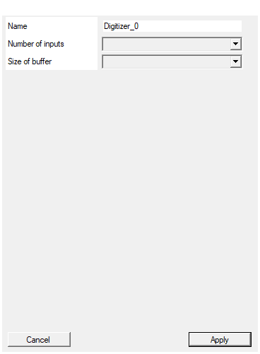
Set the name of the endpoint
Default: Digitizer_0
Set the number of input to the virtual block
Default: 1
Options: 2 4 8 16 32 64 128
Size of the readout buffer. This will determinate the maximum wave length
Default: 1024
Options: 128 256 512 1024 2048 4096 8192 16384 32768 65536 131072 262144 524288
Maximum waveform length in samples per channel. Available values: 128, 256, 512, 1024, 2048, 4096, 8192, 16384, 32768, 65536, 131072, 262144, 524288.
Note: Actual maximum waveform length is slightly less due to header overhead. Default: 1024
Usage
How It Works
The Digitizer operates as an event-driven waveform capture system:
- RUN must be HIGH to enable acquisition
- When START goes HIGH, all inputs are latched (TIMESTAMP, HITS, USER)
- While START is HIGH, waveform samples are captured on each clock cycle (if CE is HIGH)
- When START returns LOW, the captured waveform is packaged and sent to the FIFO
- The PC reads events from the FIFO via USB/Ethernet
┌──────────────────────────────────────────────────────────────────┐
│ Digitizer Data Flow │
│ │
│ IN0 ─────────►┌──────────────┐ │
│ IN1 ─────────►│ │ ┌─────────────┐ │
│ ... │ Waveform │────►│ FIFO │────► PC │
│ INn ─────────►│ Capture │ │ Buffer │ │
│ │ │ └─────────────┘ │
│ START ───────►│ │ │
│ TIMESTAMP ───►│ │ │
│ HITS ────────►│ │ │
│ USER ────────►│ │ │
│ └──────────────┘ │
└──────────────────────────────────────────────────────────────────┘
Channel Configuration
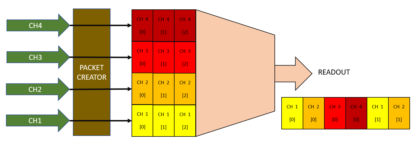
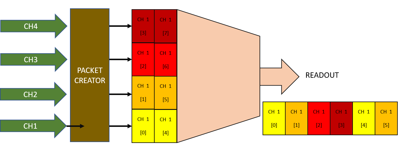
The number of channels must be a power of two (2, 4, 8, 16, 32, 64). At runtime, you can configure how many channels to actually read out (starting from CH0).
For example, if you configure 4 inputs in SciCompiler:
- Setting
enabledch = 2reads only CH0 and CH1 - Setting
enabledch = 4reads CH0, CH1, CH2, CH3
This optimizes FIFO usage when not all channels are needed.
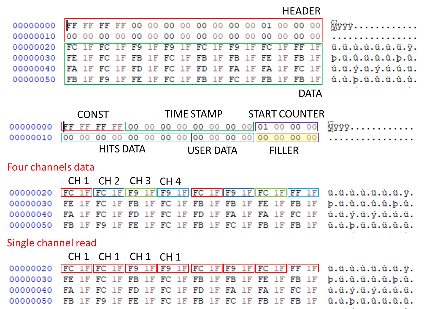
Four channel acquisition:
Single channel acquisition:
Output Data Format
Each event captured by the Digitizer contains:
| Field | Size | Description |
|---|---|---|
| Header | 32 bits | Constant value 0xFFFFFFFF (sync word) |
| Timestamp | 64 bits | Captured from TIMESTAMP input |
| Packet Index | 32 bits | Sequential event counter |
| Hits | 64 bits | Captured from HITS input |
| User | 32 bits | Captured from USER input |
| Filler | Variable | Alignment padding (see table below) |
| Waveform Data | Variable | Sample data for all enabled channels |
Filler Size
The filler field size depends on the maximum number of channels configured at compile time
(not the runtime enabledch setting):
| Number of Channels | Physical FIFO Width (DWORD) | Filler Size (DWORD) |
|---|---|---|
| 1 | 1 | 0 |
| 2 | 1 | 0 |
| 4 | 2 | 1 |
| 8 | 4 | 1 |
| 16 | 8 | 1 |
| 32 | 16 | 9 |
| 64 | 32 | 25 |
Software Integration with SciSDK
The Digitizer is fully supported by SciSDK. For complete documentation see: SciSDK Digitizer Guide
Data Processing Modes
| Mode | Description |
|---|---|
| raw | Returns raw FIFO data without processing. Useful for high-speed disk logging with post-processing. |
| decoded | Processes packets into organized waveform arrays. Easier to use for real-time analysis. |
Available Parameters
| Parameter | Access | Description |
|---|---|---|
acq_len |
R/W | Maximum samples per FIFO read (default: 1024) |
acq_mode |
R/W | blocking or non-blocking |
timeout |
R/W | Timeout in milliseconds for blocking mode (default: 100) |
data_processing |
R/W | raw or decoded mode |
enabledch |
R/W | Number of channels to read (must be ≤ max channels) |
Available Commands
| Command | Description |
|---|---|
start |
Begin acquisition |
stop |
Stop acquisition |
Decoded Buffer Structure
When using decoded mode, the SCISDK_DIGITIZER_DECODED_BUFFER structure provides:
struct SCISDK_DIGITIZER_DECODED_BUFFER {
int32_t *analog; // Waveform samples (all channels sequential)
uint64_t hits; // Hit pattern from HITS input
uint64_t timecode; // Timestamp from TIMESTAMP input
uint32_t counter; // Event counter
uint32_t user; // User data from USER input
struct {
uint32_t samples_analog; // Number of samples per channel
uint32_t valid_samples; // Actual valid samples
uint32_t channels; // Number of enabled channels
} info;
};
Data arrangement: All samples for CH0, followed by all samples for CH1, etc.
analog[0..N-1] = CH0 samples
analog[N..2N-1] = CH1 samples
analog[2N..3N-1] = CH2 samples
...
C/C++ Example
c
#include "SciSDK_DLL.h"
// Allocate decoded buffer
SCISDK_DIGITIZER_DECODED_BUFFER *buffer;
SCISDK_AllocateBuffer("board0:/MMCComponents/Digitizer_0",
T_BUFFER_TYPE_DECODED,
(void**)&buffer, _sdk);
// Configure
SCISDK_SetParameterString("board0:/MMCComponents/Digitizer_0.data_processing",
"decoded", _sdk);
SCISDK_SetParameterInteger("board0:/MMCComponents/Digitizer_0.enabledch",
2, _sdk); // Read 2 channels
// Start acquisition
SCISDK_ExecuteCommand("board0:/MMCComponents/Digitizer_0.start", "", _sdk);
// Read events
while (running) {
int ret = SCISDK_ReadData("board0:/MMCComponents/Digitizer_0",
(void*)buffer, _sdk);
if (ret == NI_OK) {
// Process waveform
printf("Timestamp: %llu\n", buffer->timecode);
printf("Hits: 0x%016llX\n", buffer->hits);
printf("User: %u\n", buffer->user);
int samples = buffer->info.samples_analog;
int channels = buffer->info.channels;
for (int ch = 0; ch < channels; ch++) {
printf("CH%d: ", ch);
for (int s = 0; s < samples; s++) {
printf("%d ", buffer->analog[ch * samples + s]);
}
printf("\n");
}
}
}
// Stop and free
SCISDK_ExecuteCommand("board0:/MMCComponents/Digitizer_0.stop", "", _sdk);
SCISDK_FreeBuffer("board0:/MMCComponents/Digitizer_0",
T_BUFFER_TYPE_DECODED, (void**)&buffer, _sdk);
Python Example
python
from scisdk.scisdk import SciSDK
sdk = SciSDK()
sdk.AddNewDevice("usb:10500", "dt5560", "board0", "RegisterFile.json")
# Allocate buffer
res, buf = sdk.AllocateBuffer("board0:/MMCComponents/Digitizer_0",
sdk.T_BUFFER_TYPE_DECODED)
# Configure
sdk.SetParameter("board0:/MMCComponents/Digitizer_0.data_processing", "decoded")
sdk.SetParameter("board0:/MMCComponents/Digitizer_0.enabledch", 2)
# Start and read
sdk.ExecuteCommand("board0:/MMCComponents/Digitizer_0.start", "")
while True:
res, buf = sdk.ReadData("board0:/MMCComponents/Digitizer_0", buf)
if res == 0:
print(f"Timestamp: {buf.timecode}")
print(f"Hits: {buf.hits:016X}")
print(f"User: {buf.user}")
samples = buf.info.samples_analog
channels = buf.info.channels
for ch in range(channels):
waveform = buf.analog[ch * samples : (ch + 1) * samples]
print(f"CH{ch}: {waveform[:10]}...") # First 10 samples
Application Notes
For complete decoding algorithms and application examples, see: https://github.com/NuclearInstruments/scicompiler-wave-digitizer
Important Notes
- The buffer size determines the maximum waveform length
- It’s not possible to acquire a waveform exactly equal to the buffer size due to header overhead
- The number of channels must be a power of two
- RUN must be HIGH for the digitizer to accept START triggers
Resources & Timing
-
Latency: Sample capture starts on START rising edge
-
Throughput: One sample per clock cycle per channel
- Uses BRAM for waveform and FIFO storage
- Number of channels must be power of two
- Channel count can be reduced at runtime via SciSDK
- Data readable via Resource Explorer or SciSDK
- Supports both raw and decoded readout modes