
DSP - BLOCK AREA
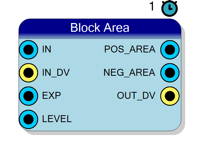
The positive, negative and absolute area of a block of N consecutive samples about a RUNTIME level driven on the LEVEL pin: with d = x - LEVEL, POS_AREA is the sum of d over the samples above the level, NEG_AREA the sum over the samples below it (so it is negative or zero), and ABS_AREA the sum of |d|, derived as POS_AREA - NEG_AREA. This is a gated integrator whose gate comes from the signal itself - the natural way to measure how much of a pulse sits above a baseline and how much undershoot follows it, with no separate discriminator. N is a power of two chosen at RUN TIME on the EXP input pin (EXP = 10 means N = 1024). No multiplier, no divider, no square root and no serial tail: the result of a block is presented exactly 2 clocks after that block’s last sample, and it is BIT EXACT. Each output has its own Q format and its own enable, which removes its pin and its logic before synthesis. IN_DV is the only qualifier and there is deliberately no CE pin. Optional BUSY / INTEGRATING / SAMPLE_COUNT status outputs. Blocks of up to 2^20 samples out of the box, 2^31 if you ask for it.
Introduction
The Block Area block chops the input stream into consecutive blocks of N
samples and, at the end of each block, publishes the area of that block above
and below a level $\ell$ driven on the LEVEL pin. With
$d_i = x_i - \ell$:
$$ A^{+} = !!\sum_{d_i > 0}!! d_i ;; (\ge 0), \qquad A^{-} = !!\sum_{d_i < 0}!! d_i ;; (\le 0) $$
$$ A^{|\cdot|} = \sum_{i=0}^{N-1} |d_i| = A^{+} - A^{-} $$
Two adders in the sample path, one subtraction at the end. No multiplier, no divider, no square root - and no division by N either: these are sums, not means.
N is a runtime input, not a property. You drive the exponent on the
EXP pin and the block size is $N = 2^{\mathrm{EXP}}$:
| EXP | N | EXP | N |
|---|---|---|---|
| 4 | 16 | 12 | 4096 |
| 6 | 64 | 16 | 65536 |
| 8 | 256 | 20 | 1048576 |
N being a power of two is what makes every division in this family an exact arithmetic shift. This block divides by nothing at all, so it simply inherits the free runtime block length: the block size can be changed while the design is running, for free.
What it is FOR
This is a gated integrator with the gate derived from the signal itself.
In pulse processing the positive area over a baseline is the integrated
pulse - the charge - and you get it without a separate discriminator, a
comparator chain or a gate signal: put the baseline on LEVEL and the block
integrates exactly the part of the waveform that is above it.
- POS_AREA - integrated charge above the level. The classic energy / amplitude measurement of a pulse over its baseline.
- NEG_AREA - the undershoot. Pole-zero cancellation errors, baseline restorer overshoot and AC-coupling droop all show up here as a growing negative area, which makes this the natural diagnostic pin for them. It is negative or zero by construction, hence its SIGNED default.
- ABS_AREA - total activity regardless of sign, $\sum |d|$: a rectifier-and-integrator in one number, and the numerator of the mean absolute deviation.
With LEVEL at 0 - which is what an unconnected pin gives you - the three
degenerate into the usual positive / negative / absolute area about zero.
Cost
One subtractor for $d = x - \ell$ and two accumulators, each (input working
width + 1 + Max Block Exponent) bits, updated at one sample per clock; in the
final state one subtraction for ABS_AREA and one requantiser per enabled
output. No multiplier, no divider, no square root, no serial arithmetic.
When to use this instead of Block Statistics
The all-in-one Block Statistics block is not deprecated and computes these same three areas among twenty other statistics. The rule is simple:
- you want several statistics of the SAME block - the areas and the mean and the counts of the same N samples - use Block Statistics. They share one accumulator set and one serial tail, so the second and third statistic are nearly free.
- you want exactly these numbers - use this block. Then you synthesise only them: the pin list, the logic and the tail are all that the areas need, and nothing else reaches the synthesiser.
Two Block Statistics blocks side by side would duplicate the accumulators; two per-operator blocks side by side duplicate them too. One Block Statistics block never does.
Pin Description
IN_DV is high.
'1'. (There is deliberately no CE pin - to stall the block,
gate this.)
EXP, so a mid-block change takes
effect on the NEXT block. A sample exactly ON the level contributes 0 to
both areas. Unconnected defaults to 0, which turns the three outputs into
the usual positive / negative / absolute area about zero.
OUT_DV clock
and on no other. Present on the symbol only when Enable POS_AREA = YES.
BUSY is still high here and falls on the next clock.
OUT_DV pulse, and it falls on the clock after. On a continuous stream it
simply stays high. Present on the symbol only when Enable BUSY = YES.
How many samples have been accumulated so far in the current block: 1 after the first, N after the N-th. It is NOT cleared at the end of a block
- it HOLDS the final count through the tail and past
OUT_DV, until the first sample of the next block takes it back to 1, so on theOUT_DVclock it reads the length of the block being presented. OnlyRESETclears it to 0. Fixed 32 bits. Present on the symbol only when Enable SAMPLE_COUNT = YES.
Properties
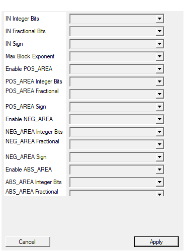
Number of INTEGER bits of the input sample (the sign, when present, uses one of them).
Integer bits of the input sample (the sign, when present, uses one of them). 1..64. Default 16. The LEVEL pin uses this same format.Default: 16
Options: 1 2 3 4 5 6 7 8 9 10 11 12 13 14 15 16 17 18 19 20 21 22 23 24 25 26 27 28 29 30 31 32 33 34 35 36 37 38 39 40 41 42 43 44 45 46 47 48 49 50 51 52 53 54 55 56 57 58 59 60 61 62 63 64
Number of FRACTIONAL bits of the input sample, i.e. the bits to the right of the binary point. Total width = integer + fractional bits, and must not exceed 64.
Fractional bits of the input sample. 0..64. Total input width must be 2..64 bits. Default 0. The LEVEL pin uses this same format.Default: 0
Options: 0 1 2 3 4 5 6 7 8 9 10 11 12 13 14 15 16 17 18 19 20 21 22 23 24 25 26 27 28 29 30 31 32 33 34 35 36 37 38 39 40 41 42 43 44 45 46 47 48 49 50 51 52 53 54 55 56 57 58 59 60 61 62 63 64
Select whether the input sample is signed (two’s complement) or unsigned.
SIGNED (two’s complement) or UNSIGNED input. Default SIGNED. An UNSIGNED input costs one extra bit internally, because a sample has to be promoted to signed before the level is subtracted from it - and it widens the internal accumulators by that bit too.Default: SIGNED
Options: UNSIGNED SIGNED
Largest block-size exponent the accumulators are sized for: the block can be up to 2^MaxBlockExponent samples long. The EXP input is clamped to this value at run time. Raising it widens the internal accumulators, and ON THE BLOCKS WHOSE SERIAL ENGINES ARE SIZED FROM THOSE ACCUMULATORS (Coefficient of Variation, SNR, Skewness, Kurtosis, Correlation, Autocorrelation, Linear Regression) it also LENGTHENS THE SERIAL TAIL – even when the runtime EXP is small. Keep it at the largest block you actually use. The default of 20 covers blocks of up to 1048576 samples.
Largest block-size exponent the accumulators are sized for: the block can be up to $2^{\text{MaxBlockExponent}}$ samples long, and theEXP input is
clamped to this value at run time. It sets the internal accumulator width -
(input working width + 1 + MaxBlockExponent) bits, which cannot overflow
for any block it allows - and widens them by one bit per unit; it does NOT
lengthen the latency of this block, which is a constant 2 clocks. Keep it
at the largest block you actually use. 1..31, default 20, i.e. blocks
of up to 1048576 samples out of the box.
Default: 20
Options: 1 2 3 4 5 6 7 8 9 10 11 12 13 14 15 16 17 18 19 20 21 22 23 24 25 26 27 28 29 30 31
YES: the POS_AREA (the sum of the deviations of the samples ABOVE the level; zero or positive) pin is present. NO: the pin AND all of its logic are removed BEFORE synthesis, so nothing is paid for it.
YES: thePOS_AREA pin exists. NO: the pin and its requantiser are removed
before synthesis - and so is its accumulator, unless ABS_AREA is on, in
which case that accumulator is needed anyway. Default YES.
Default: YES
Options: NO YES
Number of INTEGER bits of the POS_AREA output (the sign, when present, uses one of them).
Integer bits of the POS_AREA output. 1..64, default 24. It integrates up to N deviations: allow input width + 1 + block exponent bits if you want it never to clip.Default: 24
Options: 1 2 3 4 5 6 7 8 9 10 11 12 13 14 15 16 17 18 19 20 21 22 23 24 25 26 27 28 29 30 31 32 33 34 35 36 37 38 39 40 41 42 43 44 45 46 47 48 49 50 51 52 53 54 55 56 57 58 59 60 61 62 63 64
Number of FRACTIONAL bits of the POS_AREA output, i.e. the bits to the right of the binary point. Total width = integer + fractional bits, and must not exceed 64.
Fractional bits of the POS_AREA output. 0..64, total width 2..64 bits, default 0. Match the input fractional bits to keep the area in the input units.Default: 0
Options: 0 1 2 3 4 5 6 7 8 9 10 11 12 13 14 15 16 17 18 19 20 21 22 23 24 25 26 27 28 29 30 31 32 33 34 35 36 37 38 39 40 41 42 43 44 45 46 47 48 49 50 51 52 53 54 55 56 57 58 59 60 61 62 63 64
Select whether the POS_AREA output is signed (two’s complement) or unsigned.
SIGNED or UNSIGNED POS_AREA output. Default UNSIGNED: the positive area is never negative, so UNSIGNED buys one bit.Default: UNSIGNED
Options: UNSIGNED SIGNED
YES: the NEG_AREA (the sum of the deviations of the samples BELOW the level; zero or NEGATIVE, hence the SIGNED default) pin is present. NO: the pin AND all of its logic are removed BEFORE synthesis, so nothing is paid for it.
YES: theNEG_AREA pin exists. NO: the pin and its requantiser are removed
before synthesis - and so is its accumulator, unless ABS_AREA is on.
Default YES.
Default: YES
Options: NO YES
Number of INTEGER bits of the NEG_AREA output (the sign, when present, uses one of them).
Integer bits of the NEG_AREA output. 1..64, default 24. Same sizing rule as POS_AREA: input width + 1 + block exponent bits to never clip. Remember the sign bit is one of them.Default: 24
Options: 1 2 3 4 5 6 7 8 9 10 11 12 13 14 15 16 17 18 19 20 21 22 23 24 25 26 27 28 29 30 31 32 33 34 35 36 37 38 39 40 41 42 43 44 45 46 47 48 49 50 51 52 53 54 55 56 57 58 59 60 61 62 63 64
Number of FRACTIONAL bits of the NEG_AREA output, i.e. the bits to the right of the binary point. Total width = integer + fractional bits, and must not exceed 64.
Fractional bits of the NEG_AREA output. 0..64, total width 2..64 bits, default 0.Default: 0
Options: 0 1 2 3 4 5 6 7 8 9 10 11 12 13 14 15 16 17 18 19 20 21 22 23 24 25 26 27 28 29 30 31 32 33 34 35 36 37 38 39 40 41 42 43 44 45 46 47 48 49 50 51 52 53 54 55 56 57 58 59 60 61 62 63 64
Select whether the NEG_AREA output is signed (two’s complement) or unsigned.
SIGNED or UNSIGNED NEG_AREA output. Default SIGNED, and it should stay that way: the negative area is NEGATIVE or zero by construction, so an UNSIGNED format saturates it to 0 for every block that has any undershoot at all (or wraps, with Saturation off).Default: SIGNED
Options: UNSIGNED SIGNED
YES: the ABS_AREA (the sum of |deviation|, DERIVED as POS_AREA - NEG_AREA with one subtraction – but it needs BOTH accumulators, so on its own it costs as much as the other two together) pin is present. NO: the pin AND all of its logic are removed BEFORE synthesis, so nothing is paid for it.
YES: theABS_AREA pin exists, derived as POS_AREA - NEG_AREA with one
subtraction in the final state - no third accumulator, and no extra clock.
But it pulls BOTH accumulators in, whether or not their own pins are
on, so enabling it alone costs the same silicon as enabling POS_AREA and
NEG_AREA together. NO: the pin and its requantiser are removed. Default NO.
Default: NO
Options: NO YES
Number of INTEGER bits of the ABS_AREA output (the sign, when present, uses one of them).
Integer bits of the ABS_AREA output. 1..64, default 24. It is the sum of the two area magnitudes, so allow one bit more than POS_AREA or NEG_AREA if you want it never to clip.Default: 24
Options: 1 2 3 4 5 6 7 8 9 10 11 12 13 14 15 16 17 18 19 20 21 22 23 24 25 26 27 28 29 30 31 32 33 34 35 36 37 38 39 40 41 42 43 44 45 46 47 48 49 50 51 52 53 54 55 56 57 58 59 60 61 62 63 64
Number of FRACTIONAL bits of the ABS_AREA output, i.e. the bits to the right of the binary point. Total width = integer + fractional bits, and must not exceed 64.
Fractional bits of the ABS_AREA output. 0..64, total width 2..64 bits, default 0.Default: 0
Options: 0 1 2 3 4 5 6 7 8 9 10 11 12 13 14 15 16 17 18 19 20 21 22 23 24 25 26 27 28 29 30 31 32 33 34 35 36 37 38 39 40 41 42 43 44 45 46 47 48 49 50 51 52 53 54 55 56 57 58 59 60 61 62 63 64
Select whether the ABS_AREA output is signed (two’s complement) or unsigned.
SIGNED or UNSIGNED ABS_AREA output. Default UNSIGNED: the absolute area is never negative, so UNSIGNED buys one bit.Default: UNSIGNED
Options: UNSIGNED SIGNED
YES: the BUSY (high from the first sample of a block until its result is out – it COVERS THE SERIAL TAIL, and its last high clock IS the OUT_DV pulse) pin is present. NO: the pin AND all of its logic are removed BEFORE synthesis, so nothing is paid for it.
YES: theBUSY pin exists. It is high from the first sample of a block
until its result is out, tail included, and its last high clock is the
OUT_DV pulse. NO: the pin and its register are removed before synthesis.
Default NO.
Default: NO
Options: NO YES
YES: the INTEGRATING (high only while the block is ACCUMULATING; it drops as soon as the N-th sample has been taken and the tail starts, so BUSY-and-not-INTEGRATING means ‘computing’) pin is present. NO: the pin AND all of its logic are removed BEFORE synthesis, so nothing is paid for it.
YES: theINTEGRATING pin exists. It is high only while the block is
accumulating, so BUSY high with INTEGRATING low means “the samples are
all in, I am computing”. NO: the pin and its register are removed.
Default NO.
Default: NO
Options: NO YES
YES: the SAMPLE_COUNT (32 bit, how many samples have been accumulated so far in the current block: 1 after the first, N after the N-th. It is NOT cleared at the block end – it holds N until the NEXT block’s first accepted sample takes it back to 1. On a CONTINUOUS stream that happens DURING the serial tail, so at OUT_DV it reads how far into the next block the input has already got, NOT N. To capture the length of the block being presented, latch SAMPLE_COUNT on the clock INTEGRATING falls – that one always reads N) pin is present. NO: the pin AND all of its logic are removed BEFORE synthesis, so nothing is paid for it.
YES: theSAMPLE_COUNT pin exists - a fixed 32 bit count of the samples
accumulated so far in the current block, holding the final count through
the tail and past OUT_DV. NO: the pin and its counter are removed.
Default NO.
Default: NO
Options: NO YES
ROUND: round to nearest when a result has to be requantised into a coarser output format. TRUNCATE: drop the bits (cheaper, adds a negative bias).
ROUND: round to nearest when a result has to be requantised into a coarser output format. TRUNCATE: drop the bits (cheaper, adds a negative bias). Default ROUND.Default: ROUND
Options: TRUNCATE ROUND
YES: clip to the largest representable value of each output format (symmetric for signed formats). NO: wrap around.
YES: clip to the largest representable value of each output format (symmetric bounds for signed formats). NO: wrap around. It matters here: an area grows with the block length, so a format that is comfortable at EXP = 7 can overflow at EXP = 12. Default YES.Default: YES
Options: NO YES
Accuracy
The two accumulators are exact integers and the subtraction that produces
ABS_AREA is exact, so the only error in this block is the single final
requantisation of each output into the Q format you chose for it. There is no
accumulated rounding, no truncated intermediate and no approximation anywhere
in the datapath.
That is not an aspiration. The host regression (tb/block-ops/run_tb.ps1)
demands tolerance ZERO against a Python golden (tb/block-ops/ gen_golden.py) that evaluates the definitions above in exact rational
arithmetic - not “within 1 LSB”, not “within a few counts”. Any deviation at
all fails the build.
What counts as “above” and “below”
With $d = x - \ell$:
- $d > 0$ is above and contributes to
POS_AREA; - $d < 0$ is below and contributes to
NEG_AREA; - a sample sitting exactly on the level ($d = 0$) is neither. It
contributes 0 to both areas - which for an area is the same thing as
being ignored, and which is what makes the
ABS_AREAidentity below exact.
ABS_AREA is derived - and it still pulls both accumulators in
ABS_AREA is not a third accumulator. It is
$$ A^{|\cdot|} = A^{+} - A^{-} $$
computed in the final state: one subtraction, no extra adder in the sample path and no absolute-value stage. The identity is EXACT precisely because a sample on the level contributes 0 to both sides.
But it needs both accumulators. Enabling ABS_AREA alone - with the
POS_AREA and NEG_AREA pins off - costs exactly the same silicon as enabling
POS_AREA and NEG_AREA together, because both accumulators are built anyway;
all you save is two requantisers and two ports. This is the one non-obvious
cost in the block: if you are paying for ABS_AREA, you may as well take the
other two pins, they are nearly free at that point.
The LEVEL pin
LEVEL is an ordinary input pin in the input Q format, and it is always on
the symbol. It defaults to 0 when left unconnected, which degenerates the
three areas into the usual positive / negative / absolute area about zero.
LEVEL is latched on the first accepted sample of a block, exactly like
EXP, and held for that whole block. A mid-block change therefore takes effect
on the NEXT block: a block is never split between two levels, and every
area is referred to one single, well defined baseline.
The useful wiring is a baseline tracker: take MEAN from a Block Mean
block driven by the same stream and drive it into this block’s LEVEL. Because
the level is latched per block, each block’s areas are then measured against the
previous block’s baseline, which is exactly what a slow baseline restorer
wants.
Accumulator width vs output width
Internally each area is (input working width + 1 + Max Block Exponent) bits - the “+1” is the extra bit $d = x - \ell$ needs over a sample, and the working width is the input width plus one more bit if the input is UNSIGNED. The internal accumulators therefore cannot overflow for any block the exponent allows, whatever the signal does.
The output formats are your choice, and a narrow one will saturate (or wrap, if Saturation is off). To have the outputs never clip:
- size
POS_AREAandNEG_AREAat input width + 1 + block exponent integer bits; - size
ABS_AREAone bit more than either, since it is the sum of the two magnitudes.
With the 24-bit defaults and a 16-bit signed input that rule is satisfied up to blocks of $2^{7} = 128$ samples; beyond that a large enough signal can reach the saturation bound. A saturating area is a legitimate configuration - it is still monotone in the input - but you should choose it deliberately rather than discover it.
Note that the areas are sums, not means: there is no division by N here, so the value grows with the block length. That is the whole point of an area, and it is why these outputs are wide.
Accumulation and IN_DV
IN_DV is the only qualifier. It says “this clock carries a sample”: a
sample is accumulated, and counts towards N, exactly on the clocks where
IN_DV is high. Clocks with IN_DV low are ignored completely - whatever
sits on IN during them cannot corrupt the block - while the tail keeps
running, which is what you want: the tail has nothing to do with the input
stream.
Unconnected, IN_DV ties to '1', EXP ties to 10 (N = 1024) and LEVEL
ties to all zeros, so the block free-runs with nothing wired except IN.
There is deliberately no CE pin. On the all-in-one Block Statistics block an earlier revision had one, and it did not survive synthesis: with nothing but internal state gated by it, Vitis could reason the frozen path away and delete the port from the generated entity while SciCompiler’s wrapper still wired it, which failed a real Vivado build with [VRFC 10-718] formal port <ce> does not exist in entity. The whole per-operator family was built without one. To stall this block, gate its
IN_DV- a block that only accumulates onIN_DVhas no need to be frozen.
When EXP changes
EXP is clamped to Max Block Exponent and then latched on the first
accepted sample of a block, and held for that whole block. A change
therefore takes effect on the NEXT block: a block in progress always
finishes against the N it was started with, and a block is never emitted
against a different N than the one it was accumulated with. You can sweep
EXP from a register interface while the stream runs and every area stays
self-consistent - remember that the value itself scales with N, since these are
sums.
Timing: the latency contract
OUT_DV pulses for one clock, L clocks after the clock on which the N-th
sample of the block was accepted - not when that sample arrives. Every
enabled output is updated on that same clock and on no other. For this block
$$ L = 2 $$
and it is a constant: there is no serial arithmetic here at all - the two
accumulators run at one sample per clock, and the final state is one
subtraction plus the requantising shifts - so L does not depend on the input
width, on the output widths, on EXP, or on which outputs you enabled. The two
clocks are one to enter the final state and one to present the registered
results.
The rule that governs the whole family is that the tail of one block must finish before the next block completes, i.e.
$$ 2^{\mathrm{EXP}} \ge L $$
If a block completes while the previous tail is still running, that block’s
result is DROPPED: no OUT_DV for it, the accumulators are unaffected and
later blocks come out correctly, but a result is silently skipped. There is
no error pin for it.
With $L = 2$ that condition is $2^{\mathrm{EXP}} \ge 2$, i.e. EXP $\ge$ 1, so it cannot bite here: the only value that violates it is EXP = 0, a block of a single sample. The blocks where this rule really matters are the ones with a serial tail - Block RMS, Block Variance, Block Std Dev and Block Crest Factor, whose L runs to tens of clocks and whose minimum usable exponent the compiler prints in the compilation log.
Knowing where the block is: BUSY, INTEGRATING and SAMPLE_COUNT
Three optional status outputs, all defaulting to NO. They answer different questions:
INTEGRATING |
BUSY |
|
|---|---|---|
| accumulating the block | 1 | 1 |
| tail computing | 0 | 1 |
| idle | 0 | 0 |
Every output of this block is a register, so each status bit is observed on the clock after the event that sets it:
INTEGRATINGrises on the clock after the FIRST sample of a block is accepted and falls on the clock after the N-th - it is high exactly while the block is ACCUMULATING.BUSYcovers the accumulation and the tail. It rises withINTEGRATING, stays high across the tail, and its LAST HIGH CLOCK IS THEOUT_DVPULSE; it falls on the clock after.- On a continuous stream the next block starts before the previous tail
ends, so
BUSYnever drops andINTEGRATINGdips for exactly one clock per block boundary - which makes it a free block marker. SAMPLE_COUNTis a fixed 32 bits and reads 1 after the first accepted sample, N after the N-th. It is NOT cleared at the block end: it HOLDS N through the tail and pastOUT_DV, until the first sample of the next block takes it back to 1. So on theOUT_DVclock it reads the length of the block being presented - which is the useful thing to latch alongside the results, and on this block it is also the divisor you need if you want a mean area downstream. OnlyRESETclears it to 0.
Q formats
IN, LEVEL and the three areas carry fixed point formats in the usual
convention of the Fixed P. family - LEVEL shares the input format,
since it is subtracted from samples. Each result is requantised into its own
format with the selected rounding (nearest / truncate) and overflow policy
(saturate / wrap); saturation is symmetric for signed formats, as everywhere
else in the toolchain.
Signs are not a matter of taste here:
POS_AREAis never negative - UNSIGNED buys one bit, and is the default;NEG_AREAis negative or zero - it is the sum of the negative deviations, not of their magnitudes - so it needs SIGNED, which is its default. An UNSIGNEDNEG_AREAsaturates to 0 for every block that has any undershoot at all, which is almost certainly not what you meant;ABS_AREAis never negative - UNSIGNED, the default.
See “Accumulator width vs output width” above for the widths.
Enabling and disabling outputs
Each output has its own enable. Turning one off removes the pin and its requantiser before synthesis (the enables are preprocessor switches on the HLS core, so nothing reaches the synthesiser at all) and it also removes the port from the generated entity, which is why the enables take part in the IP’s unique name.
The one internal dependency to know is the one above: ABS_AREA pulls both
accumulators in, whether or not the POS_AREA and NEG_AREA pins are on.
With ABS_AREA off, disabling NEG_AREA really does remove its accumulator,
and likewise for POS_AREA.
At least one output must be enabled - the property window refuses a configuration in which all three are off, since that would leave an entity with no data ports at all.
Verification
The core is regression tested by a host-side csim harness
(tb/block-ops/run_tb.ps1) that runs one simulated clock at a time and
follows OUT_DV. The expected values come from tb/block-ops/gen_golden.py,
which evaluates the definitions above in exact rational arithmetic and shares
no algorithm with the core; the tolerance is 0. Area coverage includes
pseudo-random input at level 0, a pulse over a non-zero level (the intended
use), a signal with samples sitting exactly on the level (the case that
pins the “contributes 0 to both” convention), a LEVEL pin that changes half
way through every block in both directions - which is what proves the per-block
latch - an ABS_AREA-only configuration and a POS_AREA-only configuration,
which is also what proves the pin list and the entity port list agree for those
combinations, and a full-scale stimulus into deliberately narrow 8-bit output
formats to exercise the saturation path on all three outputs. The status
outputs are checked clock by clock against the contract above. A
cross-check compiles this core and the all-in-one block_stats.cpp into the
same binary, drives them with identical stimulus, and compares the two clock
by clock.