
RF Complex Gain (real x complex)
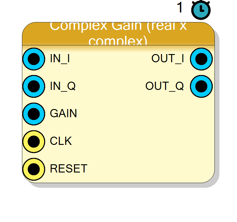
Scales a complex I/Q sample by a single real, run-time programmable gain supplied on the GAIN input pin. Typical use: manual level control, or the variable-gain element driven by an external AGC / power-measurement loop.
Introduction
The Complex Gain (real x complex) block multiplies both components of a
complex sample by the same real scalar gain:
OUT_I[n] = gain * IN_I[n]
OUT_Q[n] = gain * IN_Q[n]
Geometrically this scales the length of the IN_I + j*IN_Q vector without
rotating it, so the phase of the signal is preserved and only its amplitude
changes.
Unlike the fixed offset / coefficient blocks, gain is a real input pin
on an ap_stable interface. External logic can update it at run time (for
example an AGC loop or a register written from software). For a truly fixed
gain, tie the GAIN pin to a constant in the schematic.
Pin Description
ap_stable. Tie to a constant for a fixed gain, or drive from
an AGC / register for run-time control.
GAIN * IN_I. Signed, InputSize + GainSize
bits.
GAIN * IN_Q. Signed, InputSize + GainSize
bits.
Properties
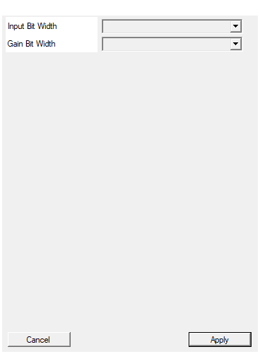
Bit width of each I/Q input (signed). Output = InputSize + GainSize.
Bit width of each signed I / Q input sample. Range 4 to 32, default 16. Output width =InputSize + GainSize.
Default: 16
Options: 4 5 6 7 8 9 10 11 12 13 14 15 16 17 18 19 20 21 22 23 24 25 26 27 28 29 30 31 32
Bit width of the gain input (signed).
Bit width of the signed gain input. Selectable from 8, 10, 12, 14, 16, 18, 20, 24, default 16. Interpret as aQ fixed-point value
(unity = 2^f) and shift the output down by f bits downstream.
Default: 16
Options: 8 10 12 14 16 18 20 24
Usage
Q-format / interpretation of the gain
The multiply is a plain signed integer product; the block does not perform any fixed-point rescaling or truncation itself:
OUT = IN * GAIN (full-precision signed product)
The output word is InputSize + GainSize bits wide, which is exactly the
size needed to hold the product of a signed InputSize-bit value and a
signed GainSize-bit value without overflow.
If you treat GAIN as a Qm.f fixed-point number (i.e. unity = 2^f),
then the product carries f extra fractional bits and you must right-shift
the output by f bits downstream to recover the same scale as the input.
For example, with a 16-bit gain used as Q1.15, feed gain = 32767 for
approximately unity and shift the result right by 15 bits.
Bit widths
Data and gain are signed two’s complement.
IN_I,IN_Q: signedInputSizebits.GAIN: signedGainSizebits (ap_stable).OUT_I,OUT_Q: signedInputSize + GainSizebits (full precision).
Latency and throughput
#pragma HLS PIPELINE II=1: one sample pair per clock.- 1-clock latency.
- Data ports use
ap_none(no handshake);GAINusesap_stable. #pragma HLS INTERFACE ap_ctrl_none port=return: no block-level control.
This block is purely combinational feed-forward: it holds no internal
state, so RESET has no effect on its arithmetic (the port exists only for
the standard HLS reset wiring).
Typical applications
- Variable-gain amplifier (VGA) element inside a larger AGC loop, driven by a gain register computed elsewhere.
- Software-controlled level trim on an I/Q stream.
- Fixed scaling by tying
GAINto a constant.
Resources & Timing
-
Latency: 1 clock cycle
-
Throughput: 1 sample per clock (II=1)
Two signed multipliers (one per channel), typically one DSP48 each.
Stateless. Output is full precision (InputSize + GainSize bits); add a
downstream shift/round/truncate stage if you need to return to the input
word width.