

State Machines - Generated HDL, Validation and Limitations
What the compiler generates for a state machine and the resulting clock-by-clock behaviour (when a transition is taken, TRANSITION_OUT, STATE_ENTERED, State Variables), the problems reported by the editor and by the compiler with their meaning, and the known limitations of the state machine editor.
What Is Generated
When the project is compiled (or simulated) every state machine produces:
- one
SUBPAGE_<machine>_<state>_bodyentity per state, compiled from the body page exactly like a sub-design page; - one top entity
FSM_<machine>infsm_<machine>.vhd, written in the HDL output folder, which instantiates all the bodies and contains the state register; - in the parent page, one instance of
FSM_<machine>per placed machine block.
Structure of FSM_<machine>
- State register:
current_state, one constantST_<state>per state, binary encoding in the order of the States list (the first created state is 0). Updated on the rising edge of CLK; RESET is synchronous and active high and loads the initial state. - Bodies: every body is instantiated and runs all the time. Each body clock
input is the machine
CLK; the default reset of the body is the machineRESET. - Outputs: a multiplexer driven by
current_stateselects, for every output port, the value computed by the body of the current state; a state that does not drive the port gives zeros. Outputs are therefore combinational functions of the current state and of the body logic (Moore or Mealy, depending on what you draw in the bodies). - Next state: for the current state, the EXIT CONDITIONs of its outgoing
transitions are tested in ascending priority order (
if / elsif); the first one at 1 gives the next state, none at 1 keeps the state. An illegal encoding ofcurrent_statereturns to the initial state.
A trimmed excerpt of the generated next-state logic and state register for a two-state machine:
vhdl
p_next_state : process(current_state, g_A_A_B, g_B_B_A)
begin
next_state <= current_state;
case current_state is
when ST_A =>
if g_A_A_B(0) = '1' then
next_state <= ST_B; -- A_B, priority 0
end if;
when ST_B =>
if g_B_B_A(0) = '1' then
next_state <= ST_A; -- B_A, priority 0
end if;
when others =>
next_state <= ST_A; -- illegal encoding: recover
end case;
end process;
p_state_reg : process(CLK)
begin
if rising_edge(CLK) then
if RESET = '1' then
current_state <= ST_A;
TRANSITION_OUT_i <= '0';
else
current_state <= next_state;
if next_state /= current_state then
TRANSITION_OUT_i <= '1';
else
TRANSITION_OUT_i <= '0';
end if;
end if;
end if;
end process;
(g_A_A_B is the EXIT CONDITION A_B computed by the body of A.)
Timing, Clock by Clock
| Event | Behaviour |
|---|---|
| EXIT CONDITION at 1 during clock n | The machine is in the destination state from clock n+1. The source state is active for the whole clock n. |
| Unconditional exit (constant 1) | The source state lasts exactly one clock. |
| Several exits at 1 | The lowest priority number wins. |
| No exit at 1 | The machine stays in the state. |
TRANSITION_OUT |
1 during the first clock in the new state, after every state change. A self-loop does not raise it. |
STATE_OUT |
The current state number, updated with the state register. |
| STATE ACTIVE | 1 in every clock in which the state is current. |
| STATE ENTERED | 1 in the first clock in the state: after every entry, self-loop included, and for the initial state while RESET is 1 and in the first clock after it. |
| VAR WRITE | The value is stored at the edge that ends the clock in which the state is active and WRITE = 1 (WRITE unconnected = every clock). The next state reads it from its first clock. |
| RESET = 1 | Initial state; TRANSITION_OUT = 0; State Variables load their reset value; every unconnected reset inside the bodies is asserted. |
Two consequences worth remembering:
- A counter or timer cleared by STATE ENTERED still shows its old value during the
entry clock. Qualify exits with
AND NOT STATE ENTERED, or clear the counter while the state is not active. - Bodies keep running when their state is not current: a free-running counter in a body continues to count. Gate it with STATE ACTIVE if it must count only in its state.
Problems and Their Meaning
The editor validates the machine continuously: the result is shown in the editor header and above the transition graph (click a problem to select the state or transition). Problems are errors: a machine with problems does not compile.
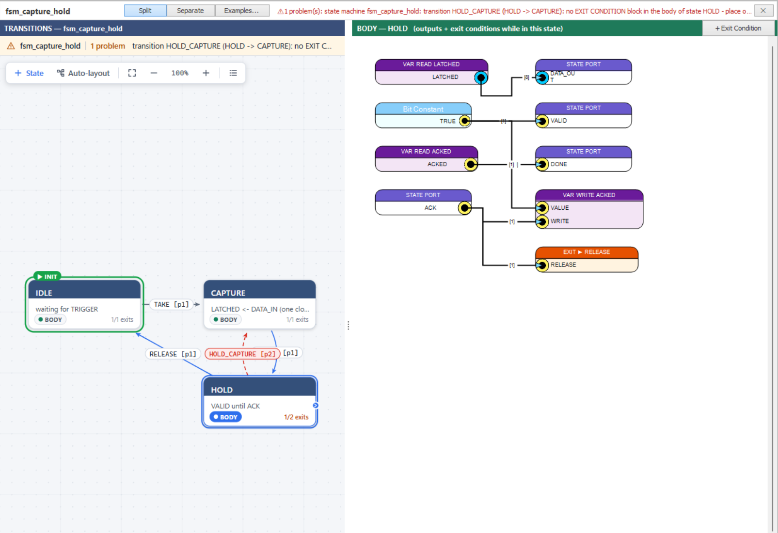
Figure 1: a new transition HOLD_CAPTURE without its EXIT CONDITION: red dashed arrow, “1/2 exits” on the card, problem in the header
| Message (excerpt) | Meaning / fix |
|---|---|
transition X (A -> B): no EXIT CONDITION block in the body of state A |
Place the EXIT CONDITION of X in A (button + Exit Condition). |
transition X (A -> B): the input of its EXIT CONDITION block ... is not connected |
Wire a 1-bit signal to the block. |
transition X ...: N EXIT CONDITION blocks in the body of state A - keep exactly one |
Delete the duplicates. |
state A: exit condition X is not bound to any transition of A - rebind it ... or delete it |
Typically a block copied with a pasted state, or left after a transition was deleted or renamed: double-click it to choose a transition, or delete it. |
state A has two outgoing transitions with priority P |
Priorities must be unique per source state. |
state A: output State Port P is driven by N blocks |
Keep one driver of P per state. |
state A: VAR WRITE V: the VALUE input is not connected |
Wire the value to write. |
state A: <block> uses the state variable V, which is not declared in this machine ... |
The variable was deleted or the block was pasted from another machine: declare it, rebind the block (double-click) or delete it. A width mismatch between block and declaration is reported in the same way. |
| port conflicts between states | The same port name with a different direction, type or width in two bodies. |
... is not allowed inside a state page / needs a dedicated clock ... |
A block that cannot live in a body (see Allowed and hidden blocks). |
the initial (reset) state is not set / the machine has no states |
Add a state / use Set as initial state. |
Update the state machine block on the parent page ... (compile) |
The placed block no longer matches the machine ports: delete it, place it again and reconnect it. |
State machine block ...: input pin X is not connected (compile) |
Every input pin except CLK and RESET must be connected on the parent page. |
Some checks of the body content (blocks not allowed in a state, VAR WRITE without VALUE, two VAR WRITE of the same variable) run when the project is compiled or simulated, not while you edit: their messages appear in the Compiler Output.
Known Limitations
- Undo: the diagram undo (Ctrl+Z) works inside a body; edits of the transition graph (states, links, names, priorities, positions) have no undo.
- Renaming a state does not rename its transitions (
IDLE_RUNstaysIDLE_RUNafterIDLEbecomesWAIT); rename them from the link properties if needed. - A placed machine block is not updated automatically when the machine ports change: delete and place it again.
- State machine pages cannot be exported / imported as
.scsfiles or duplicated from the project tree; copy states with the graph instead. - A State Port cannot change width or type in place: delete it and declare it again (State Variables can be resized with Edit).
- State Ports are
std_logic_vector(or TM) only; integer ports are not supported. - State machines cannot be nested, and a body cannot contain sub-designs.
- The project-wide Search panel does not navigate into state bodies.
- The gallery examples use 1-bit logic, a Timer and State Variables; buses inside expressions are not generated by the examples.
- Machines made with the legacy State Machine Editor are not converted.