
Waveform Averager TM
Time multiplexed twin of the Waveform Averager: same coherent time-domain averaging of triggered waveforms, but the input carries TM samples per clock on one wide bus. Everything inside is done one row of TM samples at a time, so the memories are TM times wider and TM times shallower. The averaged waveform can come out time multiplexed (one row per clock) or serialized (one sample per clock), with identical values either way.
Introduction
This is the TM variant of Waveform Averager. Everything it does — the power-of-two averaging, the clear vs cumulative history, the three output formats, the saturating overflow with optional halt, the deferred pile-up aware acquisition and the internal pre-trigger with its veto — behaves exactly as described in that block’s guide. Read it first; this page only covers what is different because of the time multiplexing.
DIN carries TM samples per clock: lane q occupies bits
(q+1)·InputBits-1 downto q·InputBits and lane 0 is the oldest sample of
the clock. One clock of the bus is one row, and the block counts rows
where the scalar block counts samples: the accumulator RAM holds TM
accumulators per row, the scratch RAM and the pre-trigger buffer hold TM
samples per row, and each of the TM lanes gets its own 36-bit accumulator and
its own overflow check.
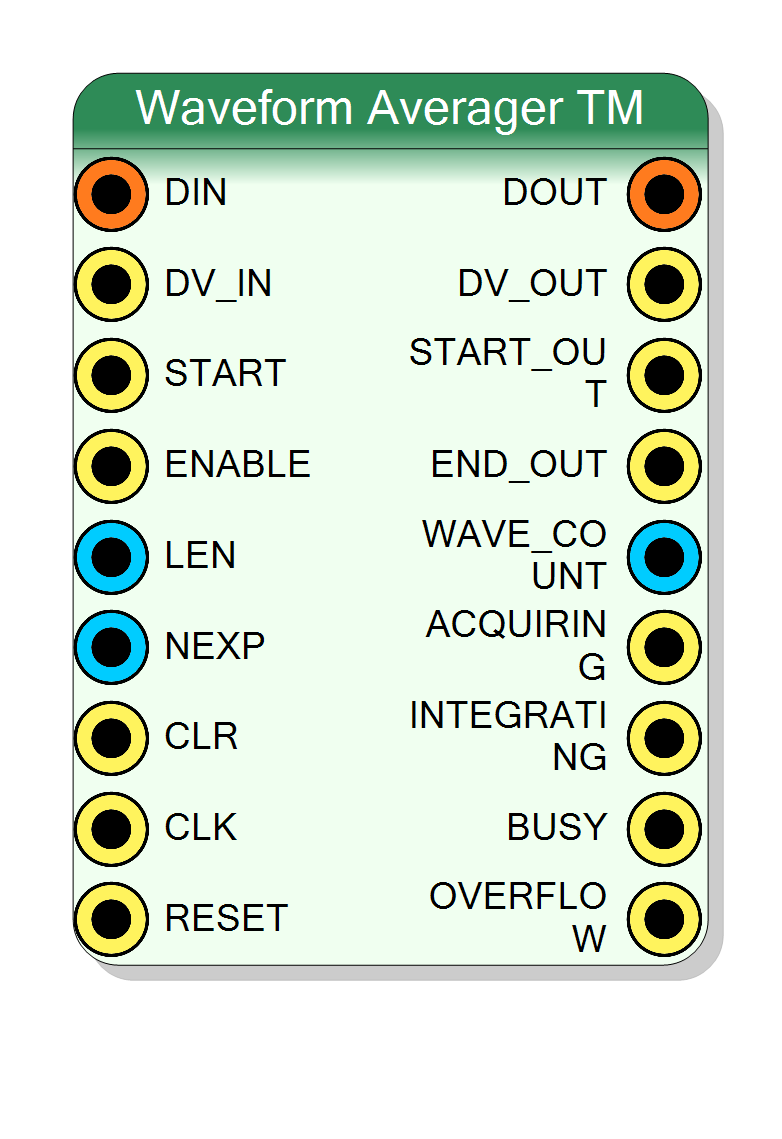
Pin Description
Properties
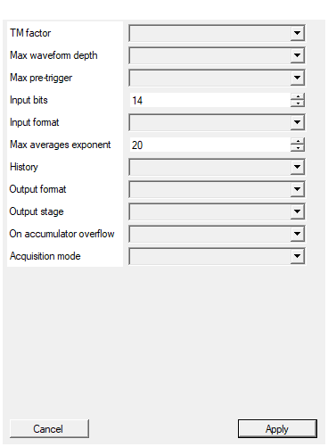
Number of samples carried on DIN per clock (lane 0 is the oldest sample of the clock). Everything inside the block is done one row of TM samples at a time, so the memories are TM times wider and TM times shallower than in the scalar Waveform Averager.
Samples carried on DIN per clock (2 .. 32). Everything inside the block is done one row of TM samples at a time, so the memories become TM times wider and TM times shallower and TM accumulators run in parallel.Default: 4
Options: 2 4 8 16 32
Maximum number of SAMPLES per waveform, power of two. Must be at least the TM factor. Sizes the accumulator RAM (MaxLength/TM rows of TM x 36 bit) and the width of the LEN input. The length actually accumulated comes from the LEN pin at run time and is truncated to a whole number of rows.
Maximum waveform length in SAMPLES (power of two, at least the TM factor). Sizes the accumulator RAM at MaxLength/TM rows and the LEN input.Default: 4096
Options: 64 128 256 512 1024 2048 4096 8192 16384 32768 65536
Depth of the internal pre-trigger buffer, in SAMPLES, power of two. 0 removes the buffer (and the PRETRIG pin) entirely. Anything else adds a circular memory of MaxPreTrigger/TM rows that continuously records the input, so the waveform can start up to this many samples BEFORE the trigger with no external delay line. Keeping it inside the block is what lets the pile-up veto cover the pre-trigger region.
Depth of the internal pre-trigger buffer in SAMPLES, power of two, or 0 to leave it out (which also removes the PRETRIG pin). Must be at least the TM factor if non-zero, since the buffer is organised in rows.Default: 0
Options: 0 32 64 128 256 512 1024 2048 4096 8192 16384 32768
Width of ONE LANE of DIN, up to 24 bit. The full input port is InputBits x TM factor. Each accumulator is 36 bit, so up to 2**(36-InputBits) full-scale waveforms can be summed before the cells overflow.
Width of ONE LANE of DIN (1 .. 24). The full input port is InputBits x TM.Default: 14
Range: 1 – 24
Interpretation of each DIN lane. Drives the accumulator arithmetic, the overflow test, the rounding of the averaged output and the saturation of the raw output modes.
Signed or Unsigned interpretation of each lane.Default: Signed
Options: Signed Unsigned
Largest exponent the runtime NEXP input can request (NEXP is clamped to it). Also sizes the WAVE_COUNT output, and in Keep-history mode it is the total count at which the epoch is closed and the accumulator restarted.
Largest exponent NEXP can request (1 .. 31). Sizes WAVE_COUNT, and in Keep-history mode it is the total at which the epoch restarts.Default: 20
Range: 1 – 31
Clear history after each output: after every output burst the accumulator is dropped, so each burst is the mean of its own 2**NEXP waveforms. Keep history (cumulative): the accumulator is never dropped and a new burst is emitted every time the TOTAL waveform count reaches the next power of two, so the divisor stays a shift and the mean stays exact. WAVE_COUNT always reports how many waveforms the burst being emitted contains.
Clear after each output, or keep cumulatively and emit whenever the total reaches the next power of two. See the scalar block’s guide.Default: Clear history after each output
Options: Clear history after each output Keep history (cumulative)
Averaged, input width: each output lane is InputBits wide and carries the accumulator divided by WAVE_COUNT, rounded half-up. Accumulator raw, 32 bit (saturated): 32 bit per lane, raw accumulator, saturated. Accumulator raw, 36 bit: 36 bit per lane, raw accumulator, exact. In the two raw modes WAVE_COUNT is the divisor the downstream logic has to apply.
Averaged at input width, or the raw accumulator at 32 or 36 bit per lane. In the raw modes WAVE_COUNT is the divisor to apply downstream.Default: Averaged, input width
Options: Averaged input width Accumulator raw 32 bit (saturated) Accumulator raw 36 bit
Time multiplexed (one row per clock): DOUT is a TM bus of TM lanes and the burst lasts LEN/TM clocks – chain it into other TM blocks. Serialized (one sample per clock): DOUT carries one sample per clock in natural order and the burst lasts LEN clocks – feed it to scalar blocks or to a DAQ endpoint. The averaged values are identical either way.
Time multiplexed (one row per clock, DOUT is a TM bus, burst LEN/TM clocks) or Serialized (one sample per clock in natural order, burst LEN clocks). Same averaged values; pick whichever matches the block downstream.Default: Time multiplexed (one row per clock)
Options: Time multiplexed (one row per clock) Serialized (one sample per clock)
Every accumulation is checked at 37 bit and the cell always SATURATES, never wraps. Stop averaging and flag: the block also halts as soon as a single lane of a single row overflows – no further waveform is accepted and no further burst is emitted until RESET or CLR. Saturate and flag, keep running: the OVERFLOW output is raised but averaging continues on saturated cells.
Cells always saturate rather than wrap and OVERFLOW always latches; this only decides whether the block additionally halts.Default: Stop averaging and flag
Options: Stop averaging and flag Saturate and flag keep running
Direct (accumulate while acquiring): the trigger starts the recording and every row is summed into the accumulator straight away. Deferred (accumulate at end, pile-up aware): the waveform is first captured into a scratch RAM and added to the accumulator only at the END of the window; a second trigger inside the captured span marks it as piled up, and the DISCARD_PILEUP input then decides whether it is thrown away. Use this to build clean pulse templates. The commit pass costs one extra waveform length of dead time.
Direct, or Deferred / pile-up aware (adds the scratch RAM, the DISCARD_PILEUP and PILEUP pins, and one waveform of dead time). Use Deferred to build clean pulse templates.Default: Direct (accumulate while acquiring)
Options: Direct (accumulate while acquiring) Deferred (accumulate at end pile-up aware)
LEN and PRETRIG are truncated to a whole row
LEN and PRETRIG are given in samples, the same units as the scalar
block, but are rounded down to a multiple of the TM factor.
This is not a shortcut. The trigger arrives on a clock, and that clock
carries TM samples at once, so which of them actually caused it is not
observable at this interface — sub-row resolution would be illusory, and
buying it would mean a barrel shifter across the lanes on both the
accumulate and the readout path. A LEN of 30 with TM = 4 therefore
accumulates 28 samples, and a PRETRIG of 6 with TM = 4 gives 4.
Output stage
- Time multiplexed (one row per clock) —
DOUTis a TM bus of TM lanes, the burst lasts LEN/TM clocks, andEND_OUTrides the last row. Chain this into other TM blocks. - Serialized (one sample per clock) —
DOUTcarries one sample per clock in natural order, the burst lasts LEN clocks, andEND_OUTrides the last sample. Feed this to scalar blocks or to a DAQ endpoint.
The two are separate hardware, selected at compile time, and produce identical averaged values — the regression checks both against the same expected numbers by unrolling the TM lanes.
What the TM factor costs and saves
At the same waveform length the accumulator RAM holds the same number of bits, reorganised: MaxLength/TM rows of TM × 36 bit instead of MaxLength rows of 36 bit. What changes is the arithmetic: TM adders and TM overflow checks run in parallel every clock, and in Averaged mode TM output scalers. Still no multiplier, no divider and no DSP — the divisor is always a power of two.
The dead time also shrinks in clocks: an output burst is LEN/TM clocks in TM output mode, and a deferred commit pass is LEN/TM clocks, because both move a whole row per clock.
Resources
One accumulator memory of MaxLength/TM rows × TM × 36 bit, plus a scratch memory of the same depth × TM × InputBits in deferred mode, plus a pre-trigger buffer of MaxPreTrigger/TM rows × TM × InputBits.
All of them are written as the standard single-clock simple-dual-port
template — synchronous read into a register, one read port, one write
port — and none is ever reset, which is a hard requirement for block RAM.
Whether they land in block RAM is still the synthesiser’s choice: no
ram_style attribute is applied and Vivado picks block vs distributed on a
size heuristic. Wide TM rows push towards block RAM, but treat any bit-count
arithmetic as an estimate, not as a measured utilisation figure.
Verified with the same self-checking GHDL regression as the scalar block
(15 TM configurations covering both output stages, TM factors 2/4/8, both
history modes, all three output formats, signed and unsigned, gapless
back-to-back waveforms, a single-row waveform, LEN truncation, the
pre-trigger and its veto). Nine deliberate mutations of the TM-specific
logic — lane packing on input and output, the serialized lane pipeline, the
sample-to-row conversion, the forwarding bypass — are all caught.