
Sequencer Generator
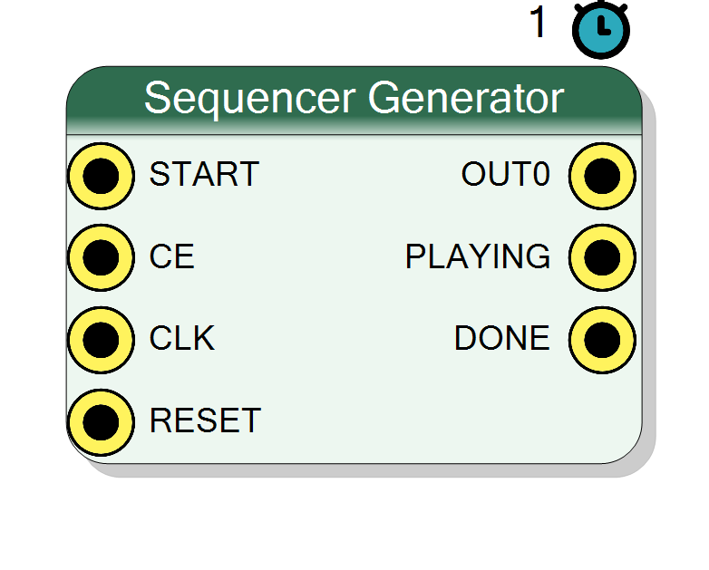
Plays back a pattern you draw. Up to 32 signals of 1 to 64 bits each are edited as waveforms in the Sequencer Designer, compiled into a ROM and replayed cycle by cycle at the full clock rate. START chooses between one run per edge and a continuous loop, CE pauses and resumes without losing position. Useful as a stimulus generator, a protocol replayer or a hard-wired control sequencer.
Introduction
The Sequencer Generator is a videotape for digital signals: you draw the waveforms you want, and the block replays them on its output pins, one sample per clock, exactly as drawn.
It is the block to reach for whenever the answer to “what should this pin do?” is a fixed schedule rather than a computation:
- stimulus for a chain you are bringing up, with no board and no software in the loop
- protocol replay: clock, chip select, data and enables of a serial device, drawn once and played back on every request
- control sequencer: gates, resets and mode changes at fixed offsets from a start
- test vectors for a block under test, generated in the GUI and replayed in silicon
Everything about the block is defined in the Sequencer Designer, a waveform editor that opens when you double click the block. The number of output pins, their names and their widths all come from what you draw there, so the symbol on the schematic changes as you edit the sequence.
Pin Description
'1' when left unconnected, so the block free runs.
'1' when left unconnected.
PLAYING and DONE.
Connected to the global reset if left unconnected.
START held high that makes it a one-clock pulse
between consecutive runs; in Edge mode it is a flag held until the next rising edge of
START.
Properties
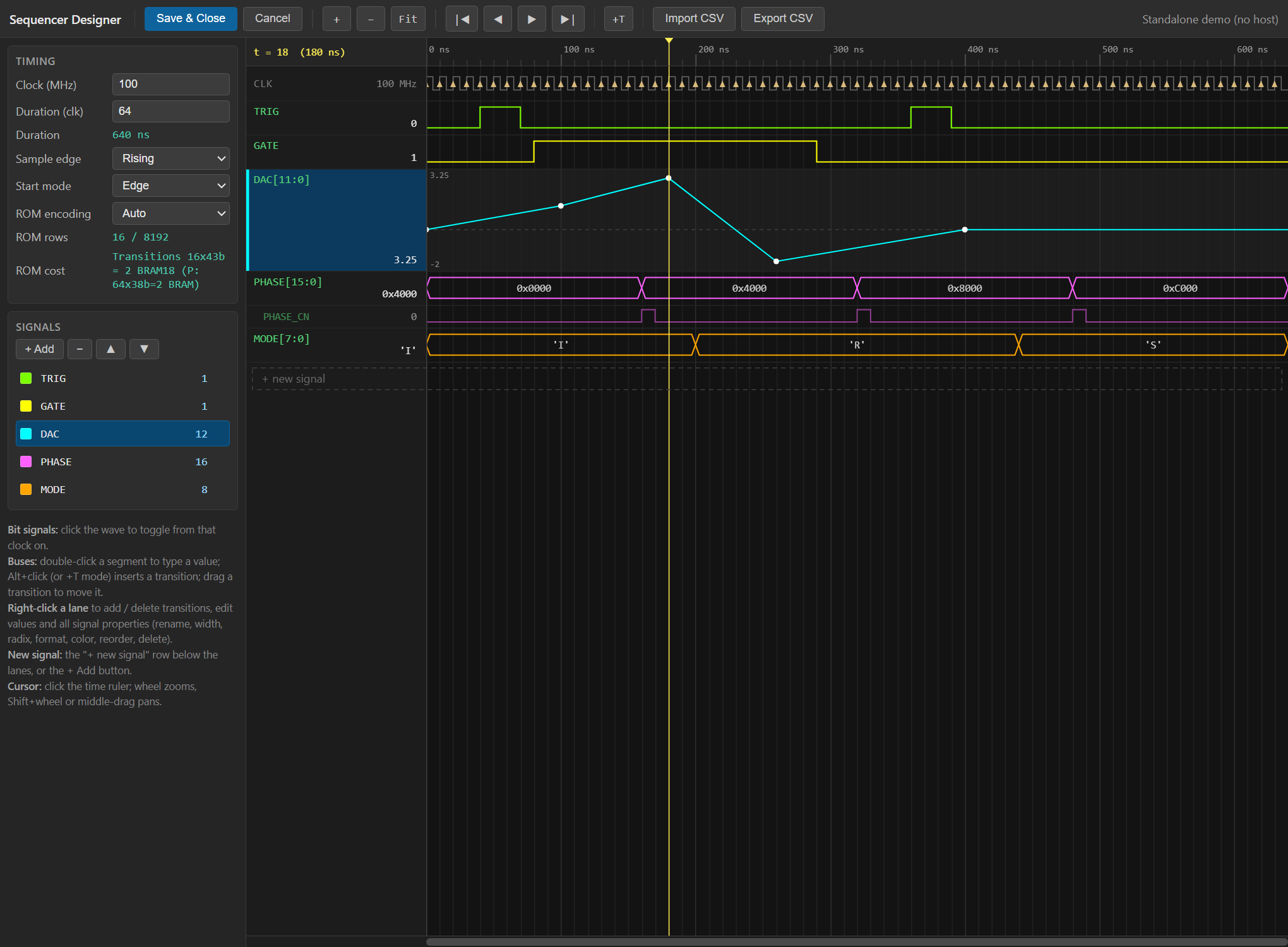
The sequence project (signals + transitions), produced by the Sequencer Designer.
The sequence itself - signals, widths, transitions and timing - as produced by the Sequencer Designer. It is not edited from the property grid: double click the block to open the waveform editor.Edge: one run per START rising edge. Level: runs while START is high (held high = loops forever). START unconnected defaults to ‘1’.
Start sensitivity. Edge: one run per rising edge ofSTART, no autostart.
Level: the sequence runs while START is high, so a constant high loops forever.
With START unconnected the input defaults to '1', which in Level mode means the
block free runs.
Default: Level
Options: Edge Level
The Sequencer Designer
Double click the block to open the editor. Each row is one output signal; the horizontal axis is time, in clock cycles of the sequence.
A signal has a name (it becomes the pin name), a width of 1 to 64 bits, a display radix and, for vectors, an optional fixed-point or floating-point interpretation used only for display and for typing values in engineering units. You add transitions where you want the value to change; between transitions the value simply holds.
The limits are:
| Item | Maximum |
|---|---|
| Signals | 32 |
| Width of one signal | 64 bit |
| Total width of all signals | 512 bit |
| Length, transition encoding | 8192 changes |
| Length, per-clock encoding | 65536 clocks |
The editor also offers pattern generators - counters, ramps, PRBS, sine and noise shapes among others - that fill a range of a signal instead of making you place every transition by hand, and an analog display mode that draws a vector lane as a curve rather than as a bus, which makes a generated ramp or sine immediately readable.
How the sequence becomes hardware
There is no generic core to configure: the block generates its own VHDL entity from
the sequence you drew, named sequencer_gen_<hash> where the hash is computed from the
whole configuration. Two blocks with the same sequence therefore share one entity, and
changing anything about the sequence produces a different one.
The sequence is stored in a ROM that is read back by a small state machine. Two encodings are available, and they behave identically cycle by cycle:
- transitions: one ROM row per change, each row carrying the new values plus the number of clocks to hold them. Cheap when the sequence is mostly flat.
- per-clock: one ROM row per clock, no hold counter. Cheaper when changes are dense, because in that case the hold field costs more than simply expanding the sequence.
The ROM encoding setting in the designer’s Timing panel selects between them, and
auto - the default - picks whichever needs fewer block RAMs. The panel shows the cost of
both encodings live, so you can see what your sequence is about to cost before compiling.
Running the sequence
While the block is idle it watches START:
- Level sensitivity: the sequence starts whenever
STARTis high. HoldingSTARThigh therefore loops forever, restarting the clock after each run. - Edge sensitivity: the sequence starts on each rising edge of
START, exactly once per edge. There is no autostart.
START and CE both default to '1' when left unconnected, so a freshly placed block in
the default Level mode free runs in a loop with no wiring at all - which is usually what
you want while bringing a design up.
PLAYING is high for the whole run. DONE rises when the last row has been played and
stays high until the next run begins: in Level mode with START held high that is a
one-clock pulse between runs, in Edge mode it is a held flag you can poll.
The outputs hold the last value of the sequence between runs. They are not cleared at the end, so the final row of your pattern is also the idle state of the block - draw it accordingly.
Pausing
CE low freezes the playback: the counters stop, the outputs hold, and lowering and
raising it again resumes exactly where it left off. It does not prevent a new run from
starting - the start condition is evaluated regardless of CE - so use START, not CE,
to keep the block idle.
RESET puts everything back to the beginning: the outputs return to the value of the
first row of the sequence, and PLAYING and DONE go low.
Change-notification outputs
Any vector signal can be given a CN flag in the designer. That adds a second, one-bit
pin named <SIGNAL>_CN which pulses for exactly one clock on every change of that
signal’s value, aligned with the first cycle in which the new value is present.
This is what you connect to the WR, DV or LOAD input of whatever consumes the
sequence, instead of drawing a strobe by hand next to every transition and keeping the
two in sync forever. The pulse is generated by comparing two registers, so it is
glitch-free; the comparison keeps running while CE is low, which means a pause that
lands exactly on a change still produces exactly one pulse when you resume.
CN outputs are only available on vectors - a one-bit signal is its own change notification.
Timing
| Item | Value |
|---|---|
| Throughput | one sequence sample per clock |
| Latency | 1 clock cycle |
| Clock edge | rising or falling, selectable in the designer |
| Resources | one ROM (block RAM or distributed, depending on size) plus a counter |
The clock frequency shown in the designer is only used to display times in seconds: the sequence is always played at one row per clock of the actual design clock. If you change the acquisition clock of the project, the sequence keeps its length in clocks, not in microseconds.
Typical use cases
- Bring-up stimulus: replay a realistic input pattern into a processing chain with no detector and no software
- Serial protocol replay: drive the clock, chip select and data lines of a DAC, a digital potentiometer or a front-end ASIC from a pattern drawn once
- Deterministic control sequences: power-up ordering, calibration pulses, gate and veto schedules at fixed offsets from a trigger
- Test vector playback for a block under test, with
PLAYINGmarking the valid window - Periodic signal generation: with Level start and
STARTtied high the block is a free running arbitrary waveform generator whose period is the length of the sequence