
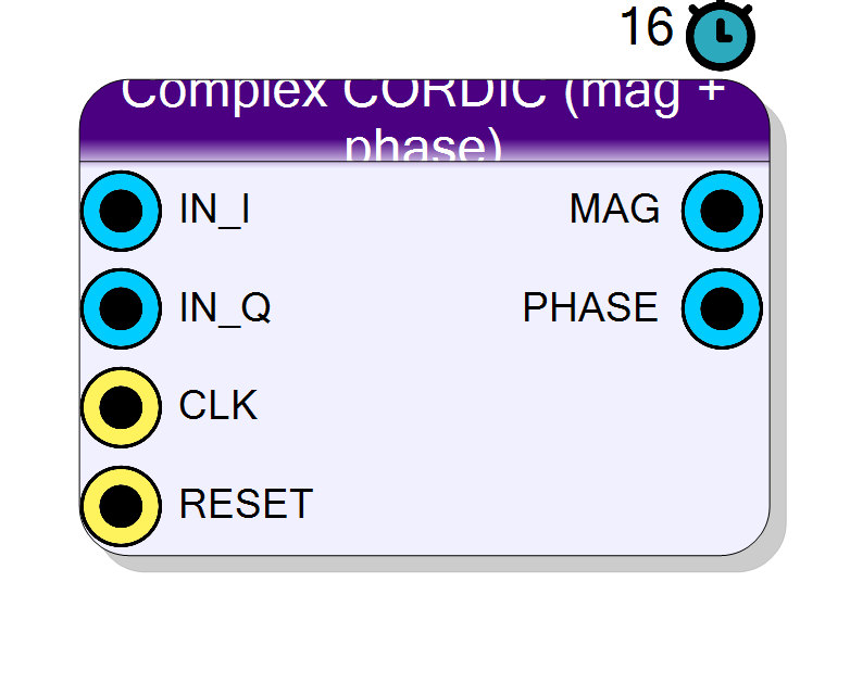
Complex CORDIC (mag + phase)
CORDIC rectangular-to-polar converter: turns a complex I/Q sample into a magnitude and a phase (atan2) using only shifts and adds. Typical use: FM discriminator (phase output), envelope / magnitude, phase measurement for a PLL or carrier-recovery loop.
Introduction
The Complex CORDIC (mag + phase) block converts a complex input
A = IN_I + j*IN_Q from rectangular to polar form:
MAG = |A| * K_cordic
PHASE = atan2(IN_Q, IN_I)
It uses the CORDIC algorithm in vectoring mode: the vector (x, y)
is rotated in successively smaller angle steps atan(2^-k) to drive y
towards zero. Each step is a shift and an add/sub, so there are no
multipliers and no lookup of trig values (only a small constant table of
the step angles).
- Every rotation that zeroes
yis accumulated into the phase registerz, so at the endz = atan2(Q, I). - The residual
xat the end equals|A|multiplied by the fixed CORDIC processing gainK_cordic ~= 1.647(the product ofsqrt(1+2^-2k)over all iterations).
For the reverse conversion (polar -> rect) see Component_ComplexPolarToRect, which shares the same phase scaling.
Pin Description
|A| scaled by the CORDIC gain (~1.647x). Unsigned,
InputSize + 2 bits.
atan2(IN_Q, IN_I), signed 16 bits with +/-Pi = +/-32768.
Properties
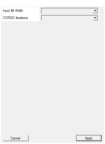
Bit width of each I/Q input (signed). MAG = InputSize+2, PHASE = 16 (Pi = 32768).
Bit width of each signed I / Q input sample. Range 4 to 32, default 16. SetsMAG = InputSize + 2; PHASE is fixed at 16.
Default: 16
Options: 4 5 6 7 8 9 10 11 12 13 14 15 16 17 18 19 20 21 22 23 24 25 26 27 28 29 30 31 32
Number of CORDIC iterations. 16 gives ~15-bit phase precision. Latency = NIter clocks.
Number of CORDIC iterations. Selectable 8, 12, 16, 20; default 16 (~15-bit phase precision). Latency equalsNIter clocks. Values
above 16 give no extra phase resolution because the 16-bit angle LUT is
exhausted past iteration 15.
Default: 16
Options: 8 12 16 20
Usage
Phase scaling
PHASE is a signed 16-bit value in which +/-Pi maps to +/-2^15:
PHASE = round(atan2(Q, I) * 32768 / Pi) (range -32768 .. +32767)
+Pi/2 = +16384, -Pi/2 = -16384, 0 = 0
This is the same wrapped, full-scale phase convention used by the NCO and the polar->rect block, so a phase from this block can be fed straight into a phase accumulator or the polar->rect converter.
Quadrant folding
Plain CORDIC vectoring only converges for the right half-plane
(x >= 0). The block first folds the input into that half-plane and
pre-loads z with the removed rotation:
x >= 0 : z = 0, (x, y) unchanged
x < 0, y >= 0 : z = +Pi/2, (x, y) -> ( y, -x) (2nd quadrant)
x < 0, y < 0 : z = -Pi/2, (x, y) -> (-y, x) (3rd quadrant)
The remaining CORDIC iterations then resolve the angle within +/-Pi/2, and the pre-load restores the full +/-Pi range.
Iterations and precision
Each iteration k = 0 .. N_ITER-1 adds/subtracts ATAN_LUT[k], the value
round(atan(2^-k) * 32768 / Pi):
k : 0 1 2 3 4 5 6 7 8 9 10 11 12 13 ...
LUT: 8192 4836 2555 1297 651 326 163 81 41 20 10 5 3 1 ...
The angle step halves each iteration, so precision improves by roughly one
bit per iteration until it hits the 16-bit phase quantum. Selectable
N_ITER values:
N_ITER phase precision latency
8 ~8 bits 8 clocks
12 ~12 bits 12 clocks
16 ~15 bits (default) 16 clocks
20 ~15 bits (LUT exhausted past k=15)
Beyond k = 15 the scaled step angle rounds to 0, so N_ITER = 16 already
reaches the resolution floor of the 16-bit phase word; 20 adds latency
without extra phase accuracy but can still tighten the magnitude estimate.
Bit widths and the CORDIC gain
IN_I,IN_Q: signedInputSizebits.MAG: unsignedInputSize + 2bits. The two extra bits hold the ~1.647x CORDIC processing gain (MAG ~= 1.647 * |A|). For RSSI / AGC the constant scale is harmless; divide by 1.647 (multiply by 0.607) downstream if a calibrated magnitude is needed.PHASE: signed 16 bits (fixed,Pi = 32768).
Latency and throughput
#pragma HLS PIPELINE II=1: one sample per clock.- The
N_ITERiterations are fully unrolled and pipelined, so latency isN_ITERclocks (default 16) while throughput stays at one sample per clock. (The schematic symbol reports a nominal latency of 16.) - All ports use the
ap_noneinterface (no ready/valid handshake).
Reset
RESET is the HLS synchronous reset (ap_rst) and clears the pipeline
registers.
Typical applications
- FM / phase discriminator : differentiate
PHASEacross samples to recover instantaneous frequency (see also Component_FMDemod). - Magnitude / envelope detector when the fixed 1.647x gain is acceptable.
- Phase measurement for a digital PLL, carrier recovery, or a coherent-detection loop.
- Polar formatting of a complex stream ahead of log/dB or quantiser stages.
Resources & Timing
-
Latency: NIter clock cycles (default 16)
-
Throughput: 1 sample per clock (II=1)
Multiplier-free: the NIter iterations are fully unrolled into a pipeline of shift-and-add stages plus a small constant angle LUT. Magnitude carries a fixed ~1.647x CORDIC processing gain. Phase precision is bounded by the 16-bit phase word (Pi = 32768).