
Custom Packet ESS
Custom Packet variant for the ESS (European Spallation Source) FEA framework. It uses the same graphical Packet Creator as the standard Custom Packet, but instead of filling a FIFO that the PC reads, it emits every packet as one 32-bit AXI-Stream frame — terminated by TLAST, optionally byte-swapped — into the board’s bulk-data link towards the ESS back-end.
Introduction
Principle of Operation
Custom Packet ESS builds packets exactly like the standard Custom Packet
block: you draw the packet in the Packet Creator, a rising edge on START
latches every input, and the packet is serialised one 32-bit row at a time.
What changes is everything downstream of the FIFO. The standard block hands the
packet to a read-out FIFO on the register bus and SciSDK pulls it over
USB/Ethernet. The ESS block hands it to an AXI-Stream master wired straight
to the board’s bulk data port (bkdata_s_axis_*), which the ESS top level
routes into the fea_top core and out over the gigabit transceivers to the ESS
back-end.
Custom Packet vs Custom Packet ESS
| Custom Packet | Custom Packet ESS | |
|---|---|---|
| Where the packet goes | read-out FIFO → PC | 32-bit AXI-Stream → ESS bulk-data link |
| Packet framing | word stream, you resync on the header constant | one TLAST-terminated AXI-Stream frame per packet |
| Software start/stop | CONFIG[0] gates acquisition |
none — the block free-runs |
RUN output pin |
yes | removed |
| Read-out registers | READ_STATUS, READ_VALID_WORDS + FIFO port |
none |
| Byte order | as laid out | optional per-field byte swap (ByteSwap, default on) |
| Input latch instant | first clock edge with START high |
one clock edge later |
| Placement | any page, including subpages | top page only |
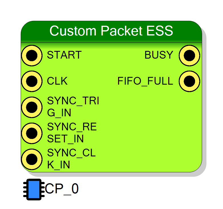
Pin Description
Packet trigger – a rising edge latches every input and starts one packet.
Double-registered, so the latch happens on the second clock edge after
START goes high (one edge later than the standard Custom Packet).
A request arriving while the FIFO is not ready is dropped.
Holding START high produces one packet, not a stream.
Shared trigger reference – rising edges increment an internal global
trigger counter in the SYNC_CLK_IN domain.
Note that no Packet Creator field emits this counter; it is maintained but not published in the packet.
Timestamp clock – the clock that increments the 32-bit TimeStamp field.
Drive it from a board-common clock when several boards must share a timebase.
The counter is crossed into the acquisition domain bit-by-bit, so prefer a
clock in the same domain as CLK if you need a strictly coherent value.
Packet in progress / no room – high while a packet is being serialised into the FIFO, and (when idle) high whenever the FIFO cannot accept a word.
Unlike the standard Custom Packet it does not carry a “stopped” term, because this block has no software run gate.
Back-pressure – high when the cross-domain FIFO is not ready
(FIFO_FULL = not tready). A START edge arriving while this is high is
dropped and the packet is lost.
It is a real back-pressure signal here, so it can be used to gate the trigger source.
Packet inputs – one pin per signal declared in the Packet Layout; the name and width of each pin come straight from the Packet Creator.
All of them are latched simultaneously, two clock edges after START
rises. They must still be valid at that moment.
Properties
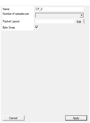
Set the name of the endpoint
Name of the memory-mapped endpoint. It names the CONFIG register in the
register map (REG_<EndpointName>_CONFIG_WR), the generated SDK functions
(CPACK_<EndpointName>_…) and the entry in RegisterFile.json.
Must be unique in the design.
Default: CP_0
Default: CP_0
Set the number of samples stored for each acquisition
Depth of the cross-domain packet FIFO, in 32-bit words (the memLength
generic). It is the burst tolerance between the packet builder and the ESS
link: a packet of N rows costs N words.
Available values: 128, 256, 512, 1024, 2048, 4096, 8192, 16384, 32768, 65536, 131072, 262144, 524288.
Default: 1024
Default: 1024
Options: 128 256 512 1024 2048 4096 8192 16384 32768 65536 131072 262144 524288
Packet Layout
The packet definition itself, edited with the Packet Creator dialog (the Edit button next to the property). It stores the rows, the fields in each row and their bit positions.
The list of input pins on the symbol is derived from this layout, so changing it rebuilds the block.
Default: empty — a block with no layout has no input pins and emits nothing useful.
Enable 32 bit byte swap
Byte-reverse every field before placing it into its 32-bit row, producing the big-endian on-the-wire order the ESS back-end expects.
| Value | Effect |
|---|---|
| True | each field is passed through byte_swap() |
| False | fields are placed exactly as laid out |
The swap is applied per field, not per finished row, and it only moves whole bytes — keep fields byte-aligned when this is enabled.
Default: True
Default: True
⚙️ Detailed Operation
Data flow
CLK (acquisition domain) BUS_CLK (bulk-data domain)
┌──────────────────────────────────────────┐ ┌─────────────────────────────┐
│ IN_a ──┐ │ │ │
│ IN_b ──┼─► latch ─► packet FSM ─► 32-bit│ │ │
│ IN_c ──┘ (on row by row word│ │ │
│ START ─► edge + TLAST on ────┼─┼──► bkdata_s_axis_tdata[31:0]│
│ detect last row │ │ bkdata_s_axis_tvalid │
│ ▲ │ │ bkdata_s_axis_tlast │
│ SYNC_CLK ─► TIMESTAMP ────┤ │ │ ◄──bkdata_s_axis_tready │
│ SYNC_TRIG ─► global cnt ──┘ │ │ │
│ SYNC_RESET ─► clears both │ │ │
└──────────────────────────────────────────┘ └─────────────────────────────┘
fwft_async_wrapper, 32 bit in / 32 bit out, depth = Samples
The cross-domain FIFO is the fwft_async_wrapper core (written to pcores/
alongside the generated packet builder). It is a first-word-fall-through
AXI-Stream FIFO carrying tdata, tlast and tuser; its output is the
bulk-data master. FIFO_FULL is simply not in_axis_tready, i.e. the FIFO has
no room left.
The packet build sequence
STARTis registered twice; the packet starts on the second clock edge afterSTARTgoes high.- On that edge every declared input is latched into a shadow register
(
l<signal>), the local packet counter increments, andBUSYgoes high. - The FSM then emits one 32-bit row per clock, in the order defined in the
Packet Creator.
FIFO_WEis asserted on every row. - On the last row of the packet
TLASTis asserted and the FSM returns to idle.BUSYfalls back tonot tready.
A packet is started only when START has a rising edge and the FIFO is
ready. There is no other gating condition.
Packet Creator fields
The layout editor is the same one used by the standard Custom Packet. Every row is 32 bits wide and can hold any mix of:
| Field | What is emitted |
|---|---|
| Constant | a fixed value (hex or binary) — the usual header / sync word |
| Input | a slice of one of the latched input signals |
| TimeStamp | TIMESTAMPs: the free-running counter clocked by SYNC_CLK_IN |
| Packet Counter | COUNTER_IN: this block’s own counter of accepted START edges |
| Packet Length | a constant equal to the total number of rows in the packet |
Bits are numbered from the most significant end: a field declared at bit
position p lands at FIFO_PORT_IN(31-p ...). Unused bits of a row are zero.
Note that Packet Counter is the local packet counter, not the SYNC_TRIG_IN
counter. The block does maintain a separate global trigger counter driven by
SYNC_TRIG_IN, but no packet field emits it — SYNC_TRIG_IN is only useful as a
shared reference if you feed it into START as well.
Byte swap
With Byte Swap enabled (the default) every field is passed through a
byte_swap() function before being placed into its row, reversing its byte
order. This produces the big-endian, on-the-wire order the ESS back-end expects
without you having to re-draw the packet.
Timestamp and the SYNC domain
TIMESTAMP is a free-running 32-bit counter in the SYNC_CLK_IN domain, cleared
by SYNC_RESET_IN, by RESET or by CONFIG[1]. It is brought into the
acquisition domain by an xpm_cdc_array_single (4 destination flops) before being
written into a packet.
That synchroniser transfers each bit independently, so if SYNC_CLK_IN is
asynchronous to CLK the sampled timestamp can be momentarily inconsistent across
a carry boundary. Driving SYNC_CLK_IN from the same clock as CLK, or from a
clock in the same domain, avoids the question entirely.
CONFIG register
CONFIG is the only register the block owns (write only), and it is not a
start/stop control:
| Bit | Value | Function |
|---|---|---|
| 0 | 1 | ignored — the ESS core has no run gate |
| 1 | 2 | Force reset. Clears the packet counter, the timestamp and the FIFO; forces BUSY high while asserted. |
| 2 | 4 | FIFO flush. Level-sensitive: while 1, the FIFO reset is held asserted. |
Software
The memory-mapped component is a generic endpoint with a single CONFIG
register — there is no FIFO read port and no READ_STATUS / READ_VALID_WORDS.
Accordingly the generated SDK only offers register pokes and a decoder skeleton:
| Generated function | Purpose |
|---|---|
CPACK_<endpoint>_RESET |
pulse CONFIG[1] |
CPACK_<endpoint>_FLUSH |
pulse CONFIG[2] |
CPACK_<endpoint>_RECONSTRUCT_DATA |
packet decoder skeleton — it is emitted with <<< … >>> placeholders and does not compile as shipped; it is meant to be edited for your layout |
The _START, _STOP and _DOWNLOAD functions that the standard Custom Packet
generates are absent, since there is nothing to start and nothing to download.
The JSON descriptor in RegisterFile.json declares this endpoint with
Type = "CustomPacket", so SciSDK will present a Custom Packet read-out API for
it. That API has nothing to read: on this block only the CONFIG register is
real, and the data leaves over the ESS link.
One bulk-data master per design
The AXI-Stream ports are bound directly to the existing top-level
bkdata_s_axis_* signals (the compiler binds, it does not declare). Nothing
arbitrates between several producers, so a design must contain exactly one
block driving the bulk-data stream — one Custom Packet ESS or one List ESS.
This is also why the block is marked top-page only: the bulk-data signals live in the top-level architecture.
Quick reference
| Item | Value |
|---|---|
| Packet layout | Packet Creator, 32-bit rows |
| Packet rate | 1 packet per (rows + 2) acquisition clocks, FIFO permitting |
| Output | 32-bit AXI-Stream, one TLAST frame per packet |
| Output clock | BUS_CLK (bulk-data domain) |
| FIFO depth | Samples 32-bit words |
| Registers | CONFIG (write) only |
| Extra file written | pcores/fwft_async_wrapper.vhd |
| Boards | R5560-B / DAQ14125-B with FPGA model Z-7035-ESS |
Resources & Timing
- Throughput: One packet per (number of rows + 2) acquisition clock cycles, FIFO permitting
- One asynchronous AXI-Stream FIFO (
fwft_async_wrapper,Sampleswords deep) plus two 32-bitxpm_cdc_array_singlesynchronisers for the timestamp and the global trigger counter. pcores/fwft_async_wrapper.vhdis written out by the compiler in addition to the generated packet-builder entity.- The only clock-domain crossings are the packet FIFO (
CLK→BUS_CLK) and the two counter synchronisers (SYNC_CLK_IN→CLK). - Requires the ESS FEA framework: the board must be an R5560-B / DAQ14125-B
with FPGA model
Z-7035-ESS, and the framework path must be configured inboards/<board>_dll/ess.txt, otherwise the compiler stops with “You need to specify the ESS FEA framework path … to use the ESS FEA framework.”