
RF Sequential FIR (programmable)
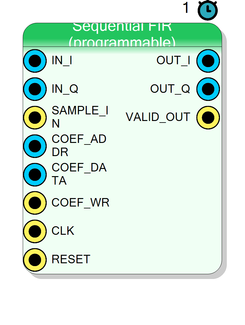
Time-shared (sequential) FIR filter with the same single-MAC architecture as seq_fir, but the coefficients live in a BRAM with a run-time write port (COEF_ADDR / COEF_DATA / COEF_WR). Reprogram the response on the fly from the fabric or the SDK — ideal for adaptive filters, matched filters whose shape depends on the sample rate, or software-defined channel selection. Real or complex I/Q.
Introduction
The Sequential FIR (programmable) block is the run-time reloadable
sibling of Component_SeqFIR. It shares the exact same time-shared MAC
datapath — one multiplier walks all NumTaps taps within the
SysClk / DataClk window, so a long filter costs a single multiplier per
channel — but instead of a compile-time coefficient ROM it stores the
taps in a small dual-port BRAM that can be rewritten while the design
runs.
SAMPLE_IN ┐ (1 pulse per new sample, gapped every ClockRatio)
IN_I / IN ┤ [ 1x time-shared MAC over NumTaps ] ── OUT_I / OUT
IN_Q ┘ ▲ coef_ram (BRAM) └─ OUT_Q
│ VALID_OUT ──
COEF_ADDR ─────────┤
COEF_DATA ─────────┤ (write h[addr] = data on COEF_WR pulse)
COEF_WR ─────────┘
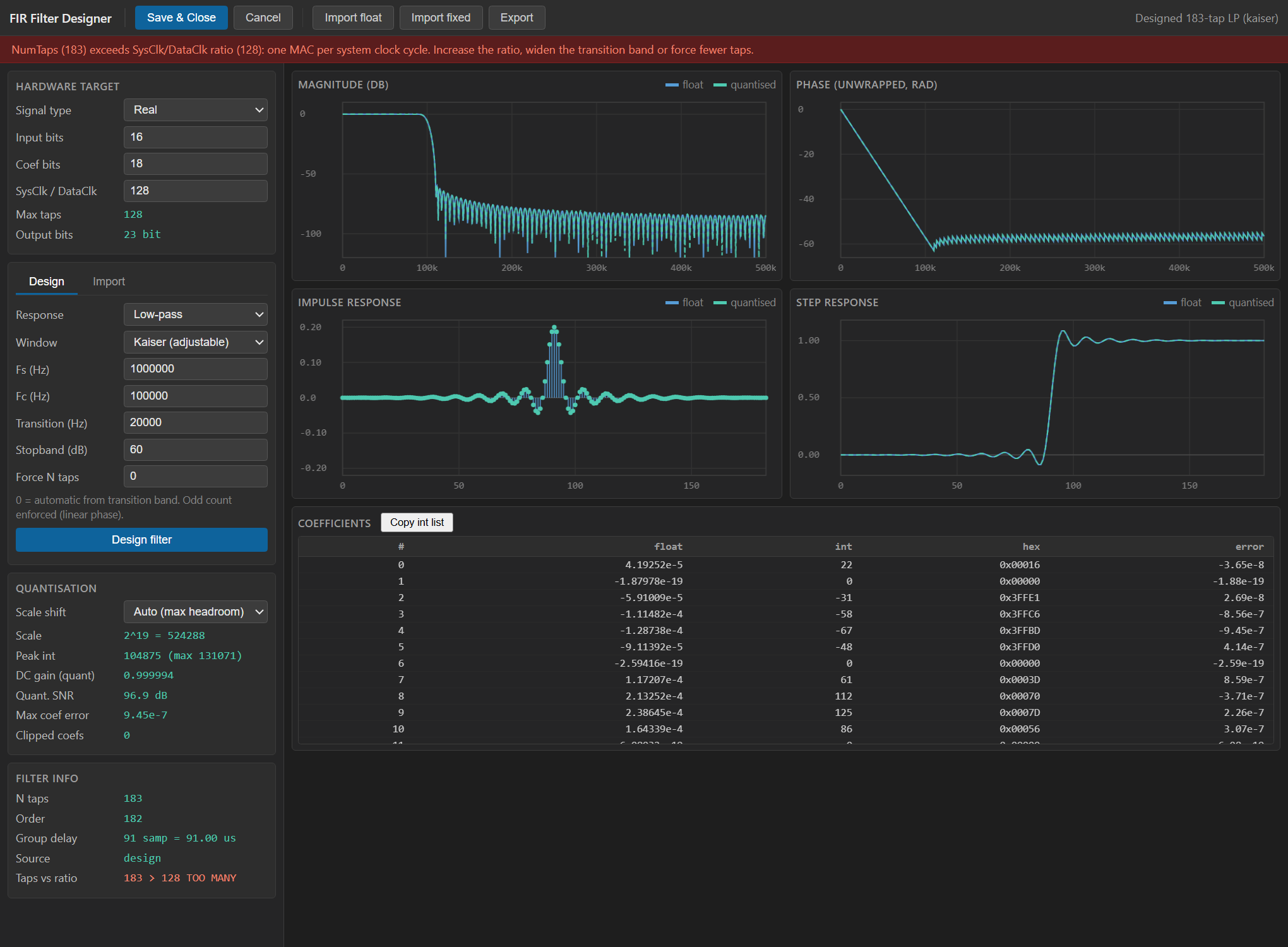
Unlike the fixed seq_fir, this block is configured through the
standard property grid (widths, tap count, clock ratio and the MAC
output shift). The FIR Designer shown above is still the recommended
companion tool: use it to prototype the response and export a quantised
integer coefficient set, then stream those coefficients into the block at
run time over the COEF_* interface. See the Visual designer note
below.
For the fixed-coefficient (ROM, no reload) version see
Component_SeqFIR (seq_fir).
Pin Description
SysClk cycle each time a new
input sample is valid. Must fire no more often than once every
NumTaps cycles (and typically once every ClockRatio cycles).
ceil(log2(NumTaps)) bits.
coef_ram[COEF_ADDR] on a COEF_WR pulse.
CLK edge,
COEF_DATA is written to tap COEF_ADDR. Hold low when not
programming.
SysClk). Default: Acquisition clock.
SysClk cycle when a new
filtered result is presented, i.e. after the MAC sweep over all
NumTaps taps completes.
Properties
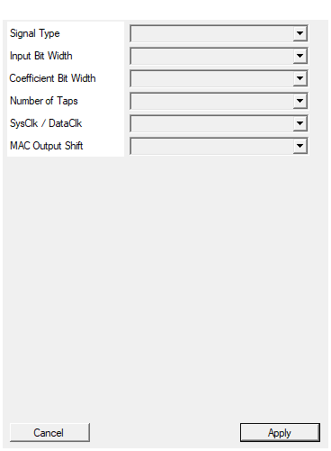
Real (single channel) or Complex (I/Q with shared coefficients).
Real (single channel,IN / OUT, one multiplier) or Complex
(I/Q on IN_I/IN_Q and OUT_I/OUT_Q sharing one coefficient
BRAM, two multipliers). Default Complex.
Default: Complex
Options: Real Complex
Bit width of the input sample(s) (signed).
Bit width of each signed input sample. Range 4 to 32, default 16.Default: 16
Options: 4 5 6 7 8 9 10 11 12 13 14 15 16 17 18 19 20 21 22 23 24 25 26 27 28 29 30 31 32
Bit width of each coefficient (signed). Sets COEF_DATA bus width.
Bit width of each signed coefficient. One of 10, 12, 14, 16, 18, 20, 24. Also sets theCOEF_DATA bus width.
Default 18.
Default: 18
Options: 10 12 14 16 18 20 24
Filter order + 1. Must be <= ClockRatio. Sets COEF_ADDR bus width.
Number of filter taps (filter order =NumTaps - 1). One of
8, 16, 24, 32, 48, 64, 96, 128, 192, 256, 384, 512, 768, 1024.
Also sets the coefficient BRAM depth and the COEF_ADDR bus width
(ceil(log2(NumTaps))). Must be <= ClockRatio. Default 64.
Default: 64
Options: 8 16 24 32 48 64 96 128 192 256 384 512 768 1024
System-clock cycles per input sample. Must be >= NumTaps.
SysClk / DataClk: system-clock cycles between input samples (the
MAC-sweep window). One of
8, 16, 32, 64, 128, 256, 512, 1024, 2048, 4096. Must be >=
NumTaps. Default 128.
Default: 128
Options: 8 16 32 64 128 256 512 1024 2048 4096
Right-shift applied to the accumulator (must match the shift used by the driver when quantising the coefficients).
Right-shift applied to the accumulator (MAC output shift). Must match the fixed-point scale the driver used when quantising the coefficients it writes. For a unity-DC-gain scale of2^(CoefSize-1)-1
use CoefSize - 1. Range 0 to 32, default 17.
Default: 17
Options: 0 1 2 3 4 5 6 7 8 9 10 11 12 13 14 15 16 17 18 19 20 21 22 23 24 25 26 27 28 29 30 31 32
Usage
Time-sharing / clock-ratio concept
Identical to seq_fir: CLK is the system clock, a new input sample is
presented once every ClockRatio system clocks and marked with a
one-cycle SAMPLE_IN pulse. On that pulse the delay line shifts, the
accumulator clears and a counter starts; each subsequent system clock
performs exactly one MAC (acc += delay[cnt] * coef_ram[cnt]); after
NumTaps cycles the shifted result is driven on the output and
VALID_OUT pulses. Because one tap is processed per clock:
NumTaps <= ClockRatio (checked at compile time)
so the core needs only one multiplier (Real) or two (Complex), independent of filter length.
Coefficient reload
The coefficients are held in a NUM_TAPS x CoefSize dual-port BRAM
(ram_2p) with a synchronous write port:
on rising CLK:
if COEF_WR = 1: coef_ram[COEF_ADDR] <= COEF_DATA (signed)
COEF_ADDRisceil(log2(NumTaps))bits — the tap index to write.COEF_DATAisCoefSizesigned bits — the new coefficient value.COEF_WRis a one-cycle write strobe.
Writes and MAC reads are independent (true dual-port), so you may reload
taps at any time. The clean recipe is to update the whole tap set in
the gap between samples (the COEF_* interface is normally quiet during
a MAC burst); as long as you do not overwrite the tap the MAC is currently
reading, the filter transitions smoothly. To load a full NumTaps-length
response, issue NumTaps writes walking COEF_ADDR from 0 to
NumTaps - 1. There is no double-buffer: the change takes effect on the
next convolution that reads the rewritten location.
Coefficients survive reset (the BRAM is not cleared by ap_rst; it powers
up to 0 and holds whatever was last written).
Bit widths and scaling
Data is signed two’s complement. Internally:
ACC_SIZE = InputSize + CoefSize + 8 (8 guard bits)
OUT_SIZE = ACC_SIZE - CoefShift
= InputSize + CoefSize + 8 - CoefShift
ADDR_SIZE = ceil(log2(NumTaps))
CoefShift is the right-shift applied to the accumulator before the
output. It is a property here (not stored by a designer), and it must
match the fixed-point scale that the host/driver used when quantising the
coefficients it writes. If you quantise with a scale of 2^(CoefSize-1)-1
(unity DC gain), use CoefShift = CoefSize - 1.
Complex vs real
- Real: pins
IN/OUT, one multiplier. - Complex:
IN_I/IN_QandOUT_I/OUT_Q, two multipliers, sharing the same coefficient BRAM (one write port updates both channels).
Visual designer
This block itself uses the standard property grid — double-clicking it
edits the hardware parameters directly, it does not open the WebView2
designer. The FIR Designer pictured in the introduction (the same tool
the fixed seq_fir opens on double-click) is nonetheless the easiest way
to produce a valid coefficient set: design the response there, let it
quantise the taps to signed CoefSize integers and note the accumulator
shift it reports, then set CoefShift to that value and stream the
integer taps into the BRAM over COEF_ADDR / COEF_DATA / COEF_WR
(typically from a register bank the SDK fills). Because the taps are not
baked in, you can swap the entire response without resynthesising the
bitstream.
Latency and throughput
#pragma HLS PIPELINE II=1: one MAC per system clock.- End-to-end latency from
SAMPLE_INtoVALID_OUTis aboutNumTapssystem clocks. - Sustained throughput is one filtered sample every
ClockRatiosystem clocks (the inputDataClkrate). - All ports use the
ap_noneinterface.
Reset
RESET (ap_rst) clears the delay line, accumulator and tap counter.
It does not clear the coefficient BRAM.
Typical applications
- Adaptive / LMS equaliser where an external engine updates taps.
- Software-defined channel-select filter: change bandwidth from the SDK without a rebuild.
- Matched filter whose shape tracks a run-time-selected symbol rate.
Resources & Timing
-
Latency: ~NumTaps system-clock cycles from SAMPLE_IN to VALID_OUT
-
Throughput: One sample every ClockRatio system clocks (the DataClk rate)
Implemented with Vitis HLS. One DSP multiplier for Real, two for
Complex, regardless of filter length (time-shared MAC, one MAC per
system clock, II=1). Coefficients live in a NUM_TAPS x CoefSize
dual-port BRAM (ram_2p) with a synchronous write port, so they are
reloadable at run time and are NOT optimised away by Vivado (DSP usage
is deterministic). A NumTaps-deep delay line (per channel) is kept in
registers / SRL. Hard constraint enforced at compile: NumTaps <= ClockRatio.