
TDC 500ps
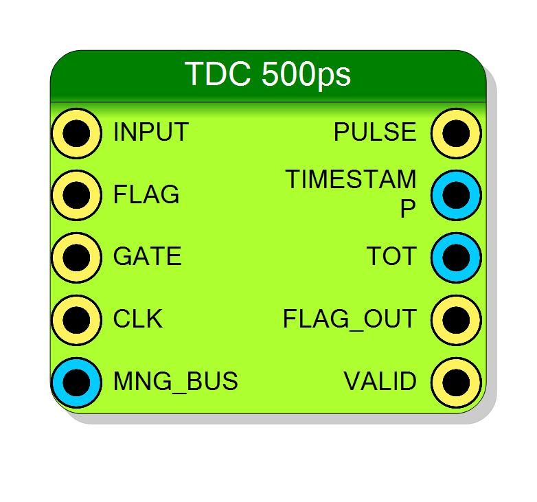
Eight–phase Time-to-Digital Converter front-end delivering 0.5 ns resolution time-stamps and optional Time-over-Threshold (ToT). It must be connected directly to an FPGA I/O pin; the controller block provides the coarse time base and the multi-phase clocks through the MNG_BUS.
Introduction
The block implements the front-end section of a two-stage Time-to-Digital Converter (TDC) working with a nominal resolution of 500 ps.
- The controller (documented separately) generates:
- a 32-bit coarse counter
abstimerunning at 125 MHz (8 ns LSB), - eight equi-spaced clock phases (
clk,clk90,sclk[3:0]) that cover the 8-ns period with 0.5-ns steps, - a reset and an optional reference flag
t_ref. All signals are packed into the 40-bit MNG_BUS.
- a 32-bit coarse counter
- This front-end samples the asynchronous hit arriving at the dedicated I/O, aligns it with the 6-phase clocks and composes a (coarse + fine) time-stamp.
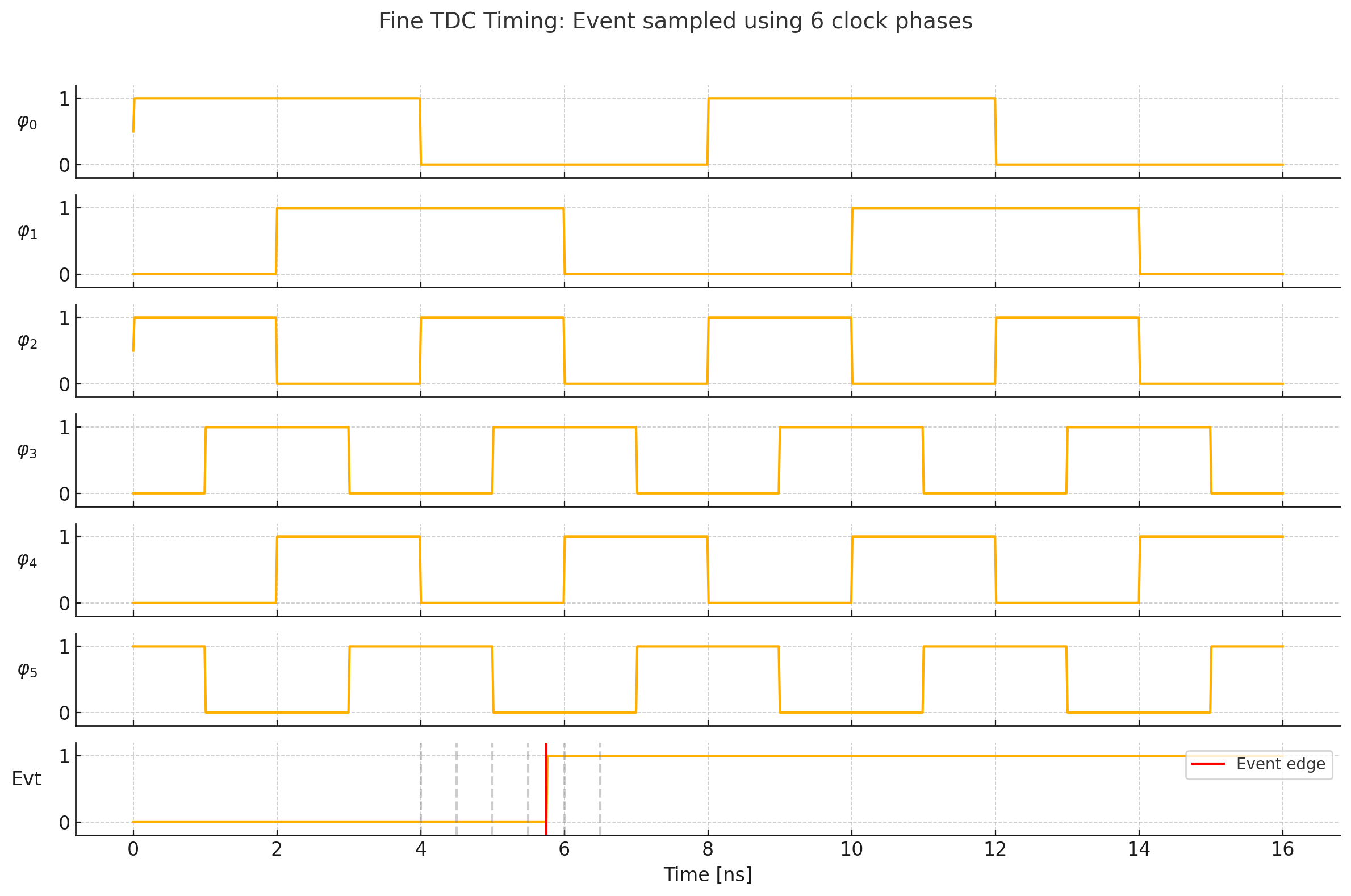
Timing diagram includes a digital event (input signal) with a rising edge at 5.75 ns, and shows how this edge is sampled by the six clock phases:
- Two from the 125 MHz domain: CLK and CLK90
- Four from the 250 MHz domain: SCLK0–SCLK270
Dashed vertical lines indicate the ideal sampling points. This mechanism allows for a time resolution finer than the system clock, leveraging phase-interleaved clocks to pinpoint event timing with sub-nanosecond precision.
A rising edge produces a PULSE on the same clock edge used for time-stamping; the formatted event (TIMESTAMP, optional TOT, FLAG_OUT) is then transferred to the user clock domain through an xpm_cdc_handshake primitive.
$$ \text{Time-stamp} = t_{\text{coarse}} ;(\text{8 ns LSB}) ;\big|; t_{\text{fine}} ;(\text{0.5 ns LSB}) $$
graph LR IO_PIN((Input I/O)) -->|6-phase sampler| FE[Front-End TDC] CTRL[Controller] --> |6-phase clock + coarse| FE FE -->|event| USER[User logic]
Pin Description
UseFlag is true the rising edge of this pin marks events and suppresses the internal T0 reference (t_ref).
run).
cdc_clk – destination clock of the user domain that receives TIMESTAMP/TOT/FLAG_OUT. Frequency is user-selectable.
40-bit management bus generated by the controller:
[TS_BITS+7] = t_ref (T0 reference flag)
[TS_BITS+6] = reset
[5] = sclk[3]
[4] = sclk[2]
[3] = sclk[1]
[2] = sclk[0]
[1] = clk90
[0] = clk
[TS_BITS+5:6] = abstime[TS_BITS-1:0]
trise (coarse + fine). Valid when VALID is high.
ToTBits. Tied to zero when UseToT is false.
t_ref or FLAG associated with the event (1 = reference hit).
cdc_clk cycle when TIMESTAMP (and, if enabled, TOT and FLAG_OUT) contain a new valid event.
Properties
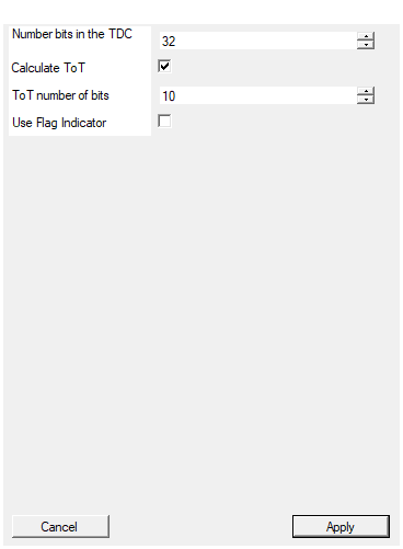
This module generate the coarse. This parameter must be matched with the Coarse Bit parameter of the TDC controller
Number of bits of the coarse counter abstime. It directly defines the width ofTIMESTAMP (coarse part) and must match the controller setting.
Default: 32
Calculate time over threshold. If checked both timestamp and ToT will be generated on falling edge of the signal
Enable Time-over-Threshold measurement. When true, the TOT field is appended to the event word and the pin TOT becomes active; extra logic and a 10-bit up-counter are instantiated.Default: True
Number of bits for the measure of the ToT
Width of the TOT result in bits (1 LSB = 0.5 ns). Larger values extend the measurable pulse length at the expense of registers and CDC width.Default: 10
If checked the T0 is ignored and in the output stream data is generated with special flag on rising edge of the flag input
Use external FLAG pin as reference marker. When enabled the internal T0 (t_ref) contained in MNG_BUS is ignored and rising edges on FLAG are forwarded to FLAG_OUT.
Default: False
Usage
Working principle
The input edge is re-synchronised twice (rising and falling edge of the 125 MHz master clock) in order to detect the exact quadrant (0…7) within the 8-ns coarse cycle. The quadrant number is encoded by the function decodecpt() that analyses the 6-bit vector built from the multi-phase clocks:
$$t_{\text{fine}} = \text{decodecpt}(\text{cpt}) \times 0.5;\text{ns}$$
vhdl
FUNCTION decode_cpt (cpt : unsigned(5 DOWNTO 0)) RETURN unsigned IS
BEGIN
-- 1111000000000000
-- FFFFRRRRRRRRFFFF
-- 0123456789ABCDEF
-- clk = cpt(5) ____--------________--------________
-- clk90 = cpt(4) ________--------________--------____
-- sclk(0) = cpt(3) ____----____----____----____----____
-- sclk(1) = cpt(2) -____----____----____----____----___
-- sclk(2) = cpt(1) --____----____----____----____----__
-- sclk(3) = cpt(0) ---____----____----____----____----_
-- 0123456789ABCDEF
CASE cpt(3 DOWNTO 0) IS
WHEN "0001" => RETURN (cpt(4) & "000");
WHEN "0011" => RETURN (cpt(4) & "001");
WHEN "0111" => RETURN (NOT cpt(5) & "010");
WHEN "1111" => RETURN (NOT cpt(5) & "011");
WHEN "1110" => RETURN (NOT cpt(5) & "100");
WHEN "1100" => RETURN (NOT cpt(5) & "101");
WHEN "1000" => RETURN (NOT cpt(4) & "110");
WHEN "0000" => RETURN (NOT cpt(4) & "111");
WHEN OTHERS => RETURN ("0000");
END CASE;
END FUNCTION;
where cpt is the sample of the 6-phase clocks at the time of the hit. The function returns a 4-bit value that is multiplied by 0.5 ns to obtain the fine time-stamp.
cpt is a 6-bit word composed of:
| Bit index | Signal | Description |
|---|---|---|
cpt(5) |
clk |
125 MHz (0°) |
cpt(4) |
clk90 |
125 MHz (90°) |
cpt(3:0) |
sclk[3:0] |
250 MHz at phases 0°, 90°, 180°, 270° |
Each bit in cpt represents the state (0 or 1) of one clock signal sampled at the moment of an input event (rising edge of the hit signal). The exact pattern of high/low bits gives us information about the timing of the event within the 8 ns clock period.
The core idea is to use the relative timing of rising edges across multiple clocks to reconstruct a finer-resolution timestamp.
Let’s define:
T_CLK = 8 ns→ 125 MHzT_SCLK = 4 ns→ 250 MHz- The total clocking system provides 8 uniformly spaced sampling points over 4 ns → 0.5 ns resolution
Decoding Logic
The function uses CASE cpt(3:0) (i.e., only the 250 MHz clocks) to detect specific edge patterns and combines that with cpt(4) and cpt(5) to disambiguate the phase.
cpt(3:0) |
Output (3-bit) | Notes |
|---|---|---|
0001 |
cpt(4) & "000" |
bin 0 or 4 (depends on clk90) |
0011 |
cpt(4) & "001" |
bin 1 or 5 |
0111 |
~cpt(5) & "010" |
bin 2 or 6 (depends on clk) |
1111 |
~cpt(5) & "011" |
bin 3 or 7 |
1110 |
~cpt(5) & "100" |
bin 4 or 0 (wrap-around) |
1100 |
~cpt(5) & "101" |
bin 5 or 1 |
1000 |
~cpt(4) & "110" |
bin 6 or 2 |
0000 |
~cpt(4) & "111" |
bin 7 or 3 |
These patterns correspond to specific falling edge sequences detected on the clocks. The additional use of cpt(4) and cpt(5) helps to resolve ambiguities caused by the overlapping phases.
The function returns a 4-bit code:
- This encodes values from 0 to 7 (i.e., 8 timing bins)
- The sign bits (
cpt(4)orcpt(5)) allow decoding whether we are in the first or second half of the clock period - Result: a timestamp with 0.5 ns resolution, even though the base on original clock is 125 MHz (8 ns)
ToT Measurement
The block can also measure the Time-over-Threshold (ToT) of the input signal.
When UseToT is asserted the block opens an internal counter at the leading edge and closes it at the trailing edge, returning the Time-over-Threshold (TOT):
$$\text{TOT} = (t_{\text{fall}} - t_{\text{rise}}) ;[\text{LSB}=0.5,\text{ns}]$$
Event formatting
The generated event is a concatenation of
{FLAG_OUT, TIMESTAMP[TS_BITS+3:0], TOT[TOT_BITS-1:0]}
and is pushed into a dual-clock handshake FIFO (xpm_cdc_handshake, DEPTH=1). VALID is asserted for one cdc_clk cycle as soon as the destination domain has accepted the word.
Timing
- Resolution: 0.5 ns (LSB of fine field).
- Front-end latency:
PULSE: 1 master-clock cycle (≈ 8 ns) after the detected edge.TIMESTAMP/VALID: 2–3 master-clock cycles + 4cdc_clksync FFs (≈ 24 ns @125 MHz) typical.
- Throughput: one hit every hold-off window (
holdoff_timeparameterised, default 10 cycles = 80 ns).
Typical applications
- Time-correlated single photon counting (TCSPC)
- Particle-detector front-ends
- High-resolution digital delay measurements