
Trigger Derivative
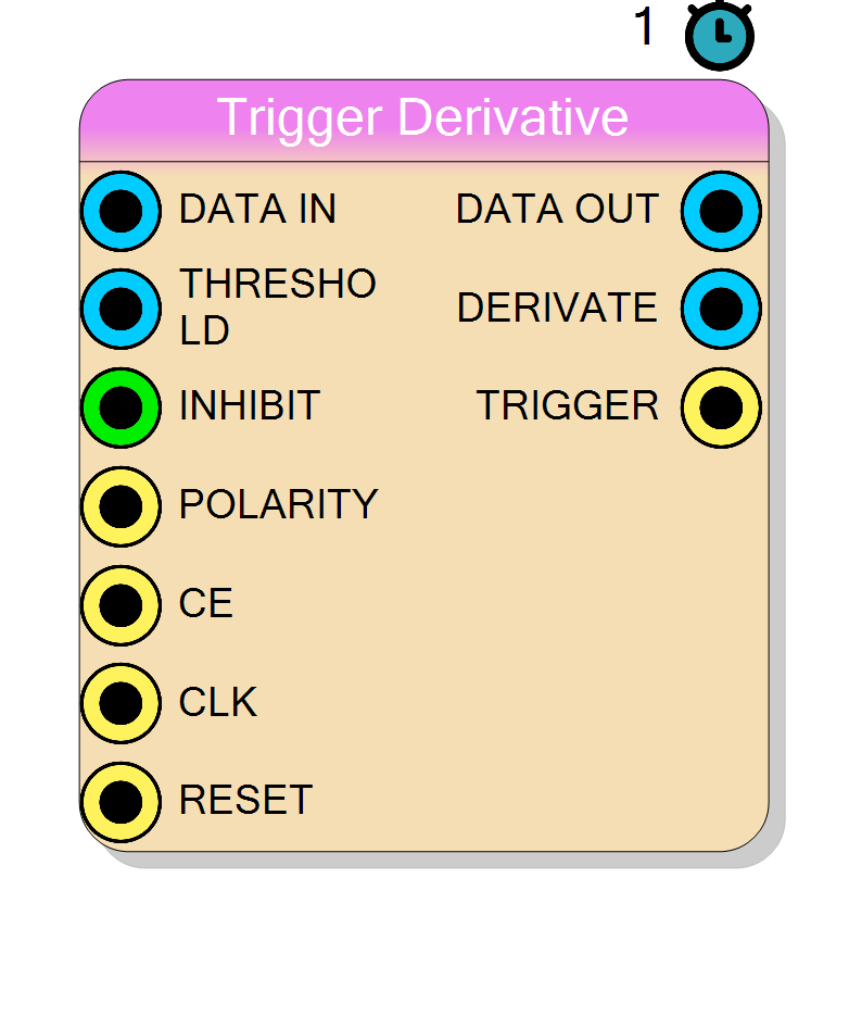
Derivative-based digital trigger with programmable word width, decorrelation delay, output delay line and selectable polarity. Generates a single-cycle trigger pulse when the derivative of the input signal exceeds a programmable threshold, with optional dead-time inhibition between successive triggers.
Introduction
The Trigger Derivative core implements a derivative-based discriminator commonly used in nuclear and particle physics data-acquisition systems. The core computes the discrete derivative of the input signal and triggers when this derivative exceeds a user-defined threshold. This approach is particularly effective for detecting fast signal edges in noisy environments, where leading-edge triggers may produce false positives on slowly varying baselines.
A key feature is the programmable Pretrigger Delay, which allows the output data to be delayed relative to the trigger, enabling capture of signal samples that occurred before the trigger event.
Pin Description
V_{thr} with bit-width equal to WordSize.
The derivative is compared against this threshold; a trigger occurs when derivative >= threshold.
TRIGGER pulse (dead-time).
Set to 0 for no inhibition.
Selects derivative polarity.
1– detect positive derivatives (rising edges)0– detect negative derivatives (falling edges) Width = 1 bit.
CE=1; otherwise the internal state is frozen and outputs keep their last value except TRIGGER, which is forced low.
CLK.
x[n] - x[n-d] where d is the Decorrelation parameter.
Properties
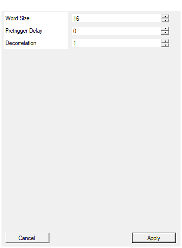
Set the number of bits of the data bus
Bit-width of the input and output data signals. Applies toDATA_IN, THRESHOLD, DATA_OUT and DERIVATE signals.
Acceptable range: 2 … 64, default 16.
Default: 16
Range: 2 – 64
Include programmable delay to embedd pretrigger logic in trigger module
Depth D of the output delay line (0 … 256). Determines the latency betweenDATA_IN and DATA_OUT.
This parameter enables pretrigger functionality: by delaying the data output, samples acquired before the trigger event can be captured.
Set to 0 for no delay (pass-through), default 0.
Default: 0
Range: 0 – 256
Set the derivative decorrelation d coefficient in the expression y = x[n] - x[n-d]
Default: 1
Range: 0 – 256
x[n] - x[n-d].
A value of 1 computes the standard first difference; larger values skip intermediate samples, providing noise rejection at the cost of reduced timing precision.
Acceptable range: 0 … 256, default 1.
Usage
Functional overview
Let
x[n]be the digitised input sample at clock cycle nd– Decorrelation delay (noise_filter parameter)D– Pretrigger Delay (data_delay parameter)V_{thr}– threshold
Derivative computation
The core computes a decorrelated derivative:
$$ \Delta x[n] ;=; x[n] - x[n-d] $$
where d is the decorrelation delay set by the Decorrelation property. A larger d value provides better noise immunity by comparing samples that are further apart in time.
Trigger decision
$$ \text{TRIGGER}[n] ;=; \begin{cases} 1 & \text{if } \Delta x[n] \ge V_{thr} \land \text{rising edge} \land \text{not inhibited} \ 0 & \text{otherwise} \end{cases} $$
The trigger is generated on the rising edge of the threshold crossing (when the derivative first exceeds the threshold after being below it). After each trigger, new triggers are inhibited for INHIBIT clock cycles.
Delay line (Pretrigger)
$$ y[n] = x[n-D] $$
where y[n] is provided on DATA_OUT and D is the pretrigger delay. This allows capturing samples that occurred before the trigger event, which is essential for waveform analysis where the signal baseline before the pulse is needed.
Note: In this example, DataDelay=2, so DATA_OUT is delayed by 2 clock cycles relative to DATA_IN.
Timing
- The derivative is computed with a latency of 1 clock cycle from the input.
TRIGGERis issued 1 clock cycle after the derivative exceeds the threshold.DATA_OUTis delayed by DataDelay clock cycles fromDATA_IN.DERIVATEoutput reflects the computed derivative with 1 clock cycle latency.
Typical applications
- Fast pulse detection in scintillator/SiPM readout systems
- Constant-fraction discriminator pre-stage
- Edge detection in digitizer applications
- Zero-crossing detection with noise rejection
- Waveform capture with pretrigger samples