
Constant Bit (True/False)
Generates a constant single-bit value representing boolean True (1) or False (0). Provides a simple source for logic high or logic low signals, useful for enable inputs, control flags, or polarity settings. Zero latency, pure combinational output.
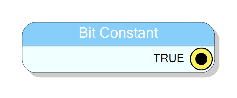
Introduction
This block generates a constant single-bit value representing a boolean state. The user selects either True (logic high, ‘1’) or False (logic low, ‘0’), and the component outputs the corresponding constant bit.
This is the simplest constant block, ideal for:
- Hardwiring enable/disable signals
- Setting polarity or inversion flags
- Providing fixed control inputs to other components
- Testing or forcing logic levels during debugging
The output is a 1-bit std_logic_vector (compatible with both std_logic
and std_logic_vector ports) with zero clock latency.
Pin Description
Constant single-bit output, always combinational (zero latency). Width: Fixed at 1 bit (std_logic_vector(0 downto 0)).
The output is hardwired to ‘1’ (True) or ‘0’ (False) based on the Value property. Compatible with both std_logic and std_logic_vector(0 downto 0) ports through automatic VHDL type conversion.
During synthesis, this output is typically optimized to a direct VDD or GND connection, consuming zero FPGA resources.
Properties
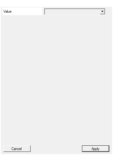
Set the value of the constant.
Boolean constant value. Choose “True” for logic high (1) or “False” for logic low (0). This determines whether the CONST output is permanently tied to VDD or GND.Default: True
Options: True False
Functional description
The component implements a constant boolean source in VHDL. The output is:
$$ \mathrm{CONST} = \begin{cases} \text{‘1’} & \text{if Value = True} \ \text{‘0’} & \text{if Value = False} \end{cases} $$
The constant is synthesized as a hardwired logic level, consuming zero FPGA resources (optimized away during synthesis in most cases).
True vs. False
- True = Logic high = Binary ‘1’ = Voltage VDD (typically 3.3V or 1.8V)
- False = Logic low = Binary ‘0’ = Voltage GND (0V)
VHDL type compatibility
The output is declared as STD_LOGIC_VECTOR(0 downto 0), which is:
- Compatible with
std_logicports (automatic conversion) - Compatible with single-bit
std_logic_vectorports - Indexable as a 1-element vector if needed
This ensures maximum flexibility when connecting to other components.
Synthesis optimization
During FPGA synthesis, constant bit sources are typically optimized away:
- True (‘1’): The connected net is tied to VDD (power rail)
- False (‘0’): The connected net is tied to GND (ground rail)
This means the component itself consumes zero logic resources (no LUTs, flip-flops, or routing). The compiler simply hardwires the destination signal.
Typical wiring examples
Enable signal (True)
Component: Some processing block
Input: ENABLE (std_logic)
Connection: Constant Bit = True
Result: Processing block permanently enabled
Active-low reset (False)
Component: Register or state machine
Input: RESET_N (active-low reset)
Connection: Constant Bit = False
Result: Reset deasserted (normal operation)
Inversion control (True)
Component: Signal inverter
Input: INVERT (polarity control)
Connection: Constant Bit = True
Result: Inverter always inverts signal
Implementation details
The VHDL implementation declares a 1-bit signal and assigns the constant:
vhdl
signal CONST : STD_LOGIC_VECTOR(0 downto 0) := "0";
CONST <= "1"; -- if Value = True
CONST <= "0"; -- if Value = False
The assignment is purely combinational and happens at power-up.
Timing
The component is purely combinational with zero latency:
| Property | Latency (clock cycles) |
|---|---|
| Constant Bit | 0 |
The output is available immediately after FPGA configuration and does not depend on any clock signal.
Typical use cases
- Enable signals: Permanently enable or disable components (e.g., ADC enable, DAC shutdown)
- Polarity control: Set inversion or active-high/low behavior (e.g., LED polarity, reset type)
- Mode selection: Choose between two operating modes (e.g., master/slave, TX/RX)
- Test inputs: Force specific logic levels during simulation or hardware debugging
- Control flags: Set configuration bits for components with boolean options
- Active-low/high signals: Provide constant assertion/deassertion for resets or chip selects
- Padding/alignment: Fill unused bits in multi-bit buses with ‘0’ or ‘1’
Design recommendations
When to use True
- Enable signals for components that should always be active
- Active-high signals that need permanent assertion
- Pull-up logic or default ‘1’ states
- Inversion flags when inversion is always required
When to use False
- Disable signals for unused components (reduces power consumption)
- Active-high signals that should remain deasserted
- Pull-down logic or default ‘0’ states
- Active-low resets/chip-selects that should be inactive
Alternative: Direct wiring
Instead of using this component, you can also:
- Use VHDL constants:
signal my_const : std_logic := '1'; - Tie signals directly in code:
enable <= '1';
However, the Constant Bit component provides:
- Visual clarity: Easy to see constant sources in block diagrams
- Easy modification: Change True/False without editing VHDL code
- Consistent style: Matches other constant components (Integer, BitVector, etc.)
Example configurations
Example 1: Enable always-on component
Value: True
Use case: Permanently enable a data processing pipeline
Output: '1' (logic high)
Example 2: Disable unused peripheral
Value: False
Use case: Turn off an unused ADC to save power
Output: '0' (logic low)
Example 3: Active-low reset deasserted
Value: False
Use case: Hold RESET_N high (inactive) for normal operation
Output: '0' → inverted externally to '1' if active-low
Example 4: Inversion control
Value: True
Use case: Always invert signal polarity
Output: '1' (invert enable)
Comparison with other constant types
| Feature | Constant Bit | Constant Integer | Constant BitVector |
|---|---|---|---|
| Width | Always 1 bit | 32 bits (INTEGER) | Configurable |
| Value range | True/False | ±2^31 | 0 to 2^N - 1 |
| Use case | Boolean flags | Counters, sizes | Bit patterns |
| Synthesis overhead | Zero (tied) | Zero (constant) | Zero (constant) |
Use Constant Bit for simple boolean control, Integer for numeric values, and BitVector for multi-bit patterns.