
Timestamp Generator
TimestampGenerator is a configurable free-running counter that provides a common timestamp reference for multiple channels. The output width is configurable from 8 to 64 bits. Multiple clock sources are supported, including an external clock input, with automatic clock domain crossing (CDC) for reliable data transfer.
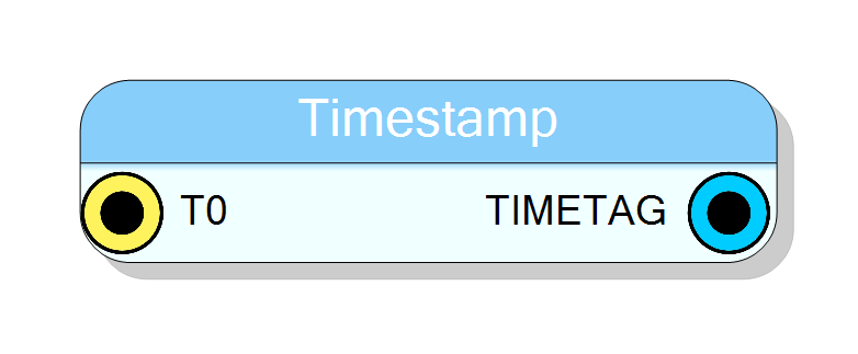
Introduction
TimestampGenerator provides a common time reference that can be shared across multiple detection channels for correlated timing measurements.
The block generates a continuously incrementing timestamp value that can be sampled by other blocks in the design to provide a consistent time reference.
The timestamp resolution is determined by the clock source frequency:
$$ \Delta t = \frac{1}{f_{\text{CLK}}} $$
The configurable output width (8-64 bits) allows trading off between timestamp range and resource usage.
Pin Description
Properties
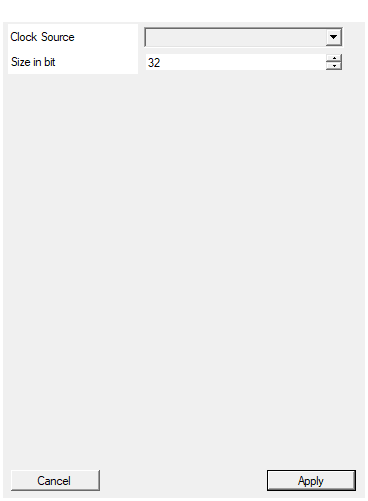
Set clock source for the timestamp generator
Selects the clock source for the timestamp counter. Available options: Board, Acquisition, 100MHz, 200MHz, 250MHz, 500MHz, External.Default: Board
Options: Board Acquisition 100MHz 200MHz 250MHz 500MHz External
Set the number of bits for the timestamp output
Number of bits for the timestamp output (8-64 bits). Larger values provide longer time range before overflow.Default: 32
Range: 8 – 64
Usage
Functional overview
TimestampGenerator operates with flexible clock domain configuration:
| Configuration | CLK_READ | CLK_EXT | Description |
|---|---|---|---|
| Board Clock | Hidden | Hidden | Counter uses board clock, output synchronous |
| Acquisition/100-500MHz | Visible | Hidden | Counter uses fast clock, output on CLK_READ |
| External | Visible | Visible | Counter uses external CLK_EXT, output on CLK_READ |

Architecture
The block consists of:
- N-bit Counter: Free-running counter (8-64 bits configurable)
- CDC Logic: Clock domain crossing for multi-clock configurations
- T0 Reset: Synchronous counter reset input
Clock Source Options
The counter clock source can be configured via the Clock Source property:
| Option | Description |
|---|---|
| Board | Use the board’s default clock (no extra clock pins) |
| Acquisition | Use the acquisition clock |
| 100MHz | Use internal 100 MHz clock |
| 200MHz | Use internal 200 MHz clock |
| 250MHz | Use internal 250 MHz clock |
| 500MHz | Use internal 500 MHz clock |
| External | Use external clock via CLK_EXT pin |
Output Size
The timestamp output width is configurable from 8 to 64 bits:
| Bits | Counter Range | Overflow Time @ 100 MHz |
|---|---|---|
| 8 | 256 | 2.56 µs |
| 16 | 65,536 | 655.36 µs |
| 32 | 4.29×10⁹ | 42.9 s |
| 48 | 2.81×10¹⁴ | 32.6 days |
| 64 | 1.84×10¹⁹ | 5845 years |
Use Cases
The TimestampGenerator is typically used when:
- Multiple independent channels need a common time reference
- Event correlation across channels is required
- A global clock needs to be distributed to multiple processing blocks