
QDC TM
Time-multiplexed Charge-to-Digital Converter (QDC) with programmable pre-trigger and post-trigger integration windows. Integrates time-multiplexed input samples over a configurable gate, providing charge (energy) measurement for pulse-height analysis applications.
Introduction
The QDC TM (Charge-to-Digital Converter, Time-Multiplexed) block performs charge integration on time-multiplexed input signals. It sums all input samples within a programmable integration window defined by pre-trigger and post-trigger parameters.
The block is designed for high-speed digitizers processing multiple samples per clock cycle (TM-phase multiplexed data), making it suitable for gamma-ray spectroscopy, scintillator readout, and other pulse-height analysis applications.
Two integration modes are supported:
- Fixed integration: The integration window has a fixed length defined by PRE_TRIGGER + POST_TRIGGER
- Variable integration: The integration window is defined by START and STOP trigger signals (Time-over-Threshold mode)
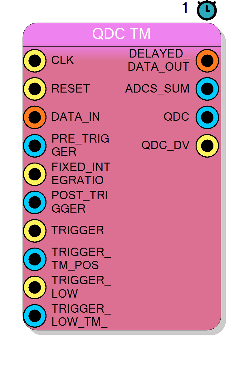
Pin Description
PreTriggerWindows × TM.
This allows capturing the rising edge of the pulse.
Integration mode selection.
1– Fixed integration: window determined by PRE_TRIGGER + POST_TRIGGER0– Variable integration: window determined by START to STOP triggers
PostTriggerWindows × TM.
Determines the length of the integration gate.
FIXED_INTEGRATION = 0 to mark the end of integration.
Ignored when FIXED_INTEGRATION = 1.
Alias: STOP
Properties
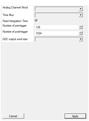
Set the analog channel word size in bits
Bit-width of each sample within the TM frame. Applies toDATA_IN and DELAYED_DATA_OUT signals.
Available values: 16, 32, 64, default 16.
Note: This property is typically hidden and auto-configured.
Default: 16
Options: 16 32 64
Set number of samples for each clock cycle
Number of parallel samples processed per clock cycle (TM factor). Available values: 2, 4, 8, 16, 32, default 4.Default: 4
Options: 2 4 8 16 32
Enable fixed integration time
Enable fixed integration time mode. When True, integration window is determined by PRE/POST_TRIGGER values. When False, integration window is determined by START/STOP triggers. Default: True.Default: True
Set the number of pre-trigger windows (each window is TM samples)
Maximum number of pre-trigger windows (each window is TM samples). Determines the maximum PRE_TRIGGER value and required delay line depth. Range: 1 … 1024, default 128.Default: 128
Range: 1 – 1024
Set the number of post-trigger windows (each window is TM samples)
Maximum number of post-trigger windows (each window is TM samples). Determines the maximum POST_TRIGGER value. Range: 1 … 65535, default 1024.Default: 1024
Range: 1 – 65535
Set the output word size in bits
Bit-width of the QDC output. Should be large enough to avoid overflow during integration. Available values: 16, 32, 64, default 16.Default: 16
Options: 16 32 64
Usage
Functional Overview
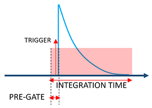
The figure shows the integration concept:
- TRIGGER: The trigger point marking the event
- PRE-GATE: Samples before the trigger that are included in the integration
- INTEGRATION TIME: The total integration window (pre-trigger + post-trigger)
The QDC computes the sum of all samples within the integration window:
$$ Q = \sum_{i=t_{start}}^{t_{stop}} x[i] $$
where $t_{start}$ = trigger - PRE_TRIGGER and $t_{stop}$ = trigger + POST_TRIGGER.
Time-Multiplexed Operation
The block processes TM_Factor samples per clock cycle. The integration window boundaries are specified in terms of individual samples (not clock cycles).
The internal logic divides the PRE_TRIGGER and POST_TRIGGER values into:
- Windows: Number of complete clock cycles
- Remainder: Position within a clock cycle (0 to TM-1)
This allows sub-clock-cycle precision for the integration boundaries.
Integration Window Calculation
Given:
PRE_TRIGGER: Number of samples before the trigger to includePOST_TRIGGER: Number of samples after the trigger to includeTM: Time-multiplexing factor
The integration window spans:
- Pre-trigger windows:
ceil(PRE_TRIGGER / TM)clock cycles before trigger - Post-trigger windows:
ceil(POST_TRIGGER / TM)clock cycles after trigger
The total number of integrated samples is approximately PRE_TRIGGER + POST_TRIGGER.
Timing Diagram
The diagram shows:
- DATA_IN_Px: Four TM phases (P0-P3) of input data
- TRIGGER_START_IN: Start trigger pulse
- TRIGGER_START_WHERE: TM position of trigger (2 = phase P2)
- SUM_OUT: Running sum of samples within each clock cycle
- INTEGRAL_OUT: Accumulated integral value
- INTEGRAL_DV_OUT: Data valid pulse when integration is complete
In this example, the trigger occurs at phase P2, so:
- First partial sum: C+D (phases P2 and P3 from trigger clock)
- Subsequent full sums: A+B+C+D (all 4 phases)
- Final partial sum: A+B (phases P0 and P1 up to stop point)
Fixed vs Variable Integration
Fixed Integration Mode (FIXED_INTEGRATION = 1):
- Integration window is determined by PRE_TRIGGER and POST_TRIGGER values
- The STOP input is ignored
- Used when pulse shape is consistent and known
Variable Integration Mode (FIXED_INTEGRATION = 0):
- Integration starts at START trigger
- Integration stops at STOP trigger
- PRE_TRIGGER still applies to shift the start point backward
- Used for Time-over-Threshold (ToT) based integration
Binary Tree Adder
The block uses a pipelined binary tree adder to sum all TM samples within each clock cycle. This architecture:
- Adds
log2(TM)clock cycles of latency - Achieves maximum throughput (1 result per clock cycle)
- Efficiently maps to FPGA DSP resources
Typical Applications
- Charge integration for scintillator/PMT/SiPM detectors
- QDC (Charge-to-Digital Converter) for nuclear physics
- Pulse-height analysis with programmable integration gates
- Time-over-Threshold based charge measurement