
Is Zero
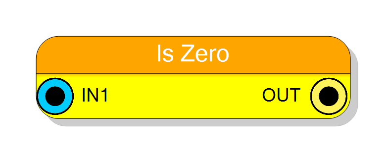
Checks whether an input value is equal to zero and outputs a boolean result. Optimized single-input comparator with configurable word size and optional output register for timing closure.
Introduction
This block performs a zero-detection operation on an input value. The output is a single bit that indicates whether the input is zero:
$$ \mathrm{OUT} = \begin{cases} 1 & \text{if } \mathrm{IN1} = 0 \ 0 & \text{otherwise} \end{cases} $$
This is an optimized version of the Equal comparator specifically for comparing against zero, which is a common operation in digital systems.
Pin Description
Comparison result output.
- ‘1’ when IN1 equals zero
- ‘0’ otherwise Width: 1 bit
Properties
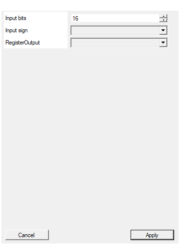
Set the number of bits of the input
Number of bits for the input value. Range: 2-2048 bits. Determines the width of the value being checked.Default: 16
Range: 2 – 2048
Select the sign/unsign of the input
Selects the interpretation of input value: UNSIGNED (default) or SIGNED (two’s complement). For zero detection, this does not affect the result.Default: UNSIGNED
Options: UNSIGNED SIGNED
Enable one pipeline stage adding a register
Adds an output register stage. Disable (combinational, zero latency) or Enable (registered, 1 clock cycle latency) for timing closure.Default: Disable
Options: Disable Enable
Functional description
The Is Zero comparator checks whether the input value is all zeros. This is equivalent to comparing IN1 against a constant zero value, but implemented more efficiently in hardware.
Operation
$$ \mathrm{OUT} = (\mathrm{IN1} == 0) $$
The component performs a NOR operation across all input bits: $$ \mathrm{OUT} = \overline{\mathrm{IN1}[N-1] \lor \mathrm{IN1}[N-2] \lor \ldots \lor \mathrm{IN1}[0]} $$
Hardware Optimization
Zero detection is typically implemented using a multi-input NOR gate or a reduction tree, which is more efficient than a full comparator with two inputs.
Latency and Timing
| RegisterOutput | Latency (clock cycles) |
|---|---|
| Disable | 0 |
| Enable | 1 |
- Disable: Purely combinational logic, zero latency.
- Enable: One register stage added for timing closure in high-speed designs.
Typical use cases
- Null or empty value detection
- Counter termination conditions
- Division by zero detection
- Result validation in arithmetic operations
- State machine idle detection