
Complex Magnitude-Squared |A|^2
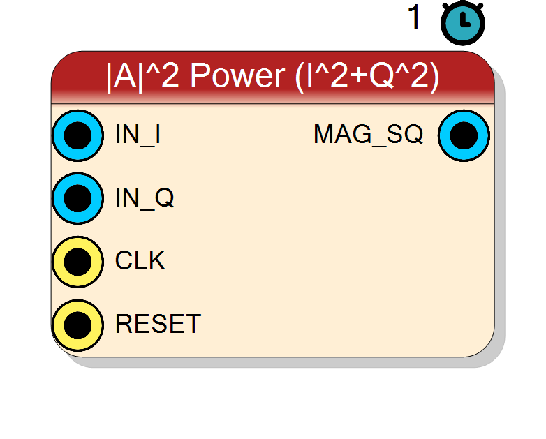
Instantaneous power of a complex I/Q sample, |A|^2 = I^2 + Q^2, computed in full precision with two multipliers. Typical use: linear power / RSSI detector, energy term for a CFAR or threshold block.
Introduction
The Complex Magnitude-Squared block computes the instantaneous power
of the complex input sample A = IN_I + j*IN_Q:
MAG_SQ[n] = IN_I[n]^2 + IN_Q[n]^2 = |A[n]|^2
This is the squared envelope of the signal. Because no square root is
taken it is exact and cheap: two InputSize x InputSize multipliers and
one adder, one clock of latency. Use it whenever a relative power figure
is enough (thresholding, RSSI, peak search) and you can tolerate the value
being in |A|^2 units rather than linear |A|.
For the linear magnitude |A| see Component_ComplexMagApprox (cheap
approximation) or Component_ComplexAtan2 (CORDIC, exact up to the fixed
gain). For a smoothed / averaged power reading see
Component_ComplexPowerMeter.
Pin Description
I^2 + Q^2. Signed, 2*InputSize + 1 bits;
value is always >= 0.
Properties
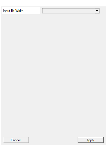
Bit width of each I/Q sample (signed).
Bit width of each signed I / Q input sample. Range 4 to 32, default 16. The output width tracks this as2*InputSize + 1.
Default: 16
Options: 4 5 6 7 8 9 10 11 12 13 14 15 16 17 18 19 20 21 22 23 24 25 26 27 28 29 30 31 32
Usage
Mathematical model
MAG_SQ = I^2 + Q^2
Inputs are treated as signed two’s-complement. The two partial
products I*I and Q*Q are each 2*InputSize bits; their sum needs one
extra bit, so the output is 2*InputSize + 1 bits. The result is always
non-negative but is carried on a signed vector for uniformity with the
rest of the RF library (the sign bit is always 0).
Bit widths
IN_I,IN_Q: signedInputSizebits.MAG_SQ: signed2*InputSize + 1bits (never negative).
With the default InputSize = 16 the output is 33 bits. No precision is
lost; truncate the low bits downstream if you need a narrower word.
Latency and throughput
#pragma HLS PIPELINE II=1: one result per clock.- 1-clock latency (register stage after the multiply/add).
- All ports use the
ap_noneinterface (no ready/valid handshake).
Reset
RESET is the HLS synchronous reset (ap_rst). The block is
combinational plus one output register; reset simply clears that register.
Typical applications
- Linear power / RSSI detector after a mixer + channel filter.
- Energy term feeding a threshold, CFAR or squelch decision.
- Envelope-squared for pulse detection where
sqrtis unnecessary. - Pair with an external
log2to obtain a dB reading.
Resources & Timing
-
Latency: 1 clock cycle
-
Throughput: 1 sample per clock (II=1)
Two DSP48 multipliers (I*I, Q*Q) and one adder. No square root, no
LUT. Fully pipelined. Output is exact full-precision |A|^2.