
Counter (Both Edges)
Synchronous edge counter that counts both rising and falling edges on an input signal. Effectively doubles the counting rate compared to single-edge counters. Features gated counting control and overflow detection. Operates synchronously to system clock. Configurable counter width from 8 to 64 bits.
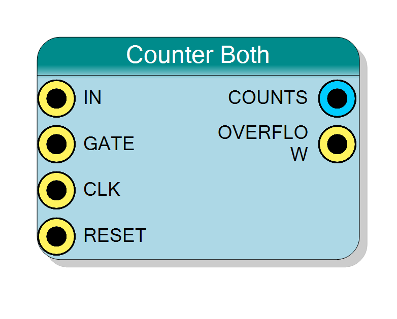
Introduction
This block counts both rising and falling edges on the IN input signal. Each complete transition cycle (0→1→0 or 1→0→1) increments the counter twice.
Key features:
- Counts both rising (0→1) and falling (1→0) edges
- Double counting rate vs single-edge counters
- Synchronous operation (glitch-immune)
- Optional gating control via GATE input
- Overflow detection
- Configurable counter width (8-64 bits)
Operation:
- Detects both rising and falling edges on IN (synchronized to CLK)
- Increments COUNTS by 1 for each edge detected (either polarity)
- GATE input enables/disables counting
- OVERFLOW pulses when counter wraps around
$$ \mathrm{COUNTS}(n+1) = \begin{cases} \mathrm{COUNTS}(n) + 1 & \text{if Any Edge on IN and GATE=‘1’} \ \mathrm{COUNTS}(n) & \text{otherwise} \end{cases} $$
Pin Description
Input signal to count.
Both rising (0→1) and falling (1→0) edges are counted. Each complete cycle produces 2 counts.
Synchronization: Signal sampled on CLK rising edge. Glitches shorter than one clock period ignored.
Frequency limit: Maximum input frequency = CLK_Frequency / 2
Count rate: For frequency f, generates 2f counts per second
Edge detection: Any transition (change in state) increments counter.
Gate control input (active high).
- ‘1’ = Counting enabled (all edges counted)
- ‘0’ = Counting disabled (all edges ignored, count holds)
Useful for measurement windows and conditional counting.
Default: Connects to ‘1’ if left unconnected (always enabled).
Clock input.
Samples IN signal, clocks edge detection, updates counter.
Must be at least 2× the maximum IN frequency for reliable edge detection (Nyquist criterion).
Counter increments when any edge detected and GATE=‘1’.
Default: Connects to global clock if left unconnected.
Synchronous reset input (active high).
- ‘1’ = Reset counter to 0, clear overflow flag
- ‘0’ = Normal operation
Resets counter regardless of IN and GATE states.
Default: Connects to global reset if left unconnected.
Current count output (unsigned integer).
Contains the number of edges (both rising and falling) detected since last reset.
Width: Configured by Bit Number property
Behavior:
- Increments by 1 for each edge on IN (when GATE=‘1’)
- Each input cycle produces 2 counts (rising + falling)
- Wraps to 0 after reaching maximum (2^BitNumber - 1)
- Holds value when GATE=‘0’
- Resets to 0 on RESET=‘0’
Frequency calculation: Input_Freq = COUNTS / (2 × Measure_Time)
Registered output, stable and glitch-free.
Overflow flag output (single-cycle pulse).
Pulses high for one clock cycle when counter wraps from maximum value (2^BitNumber - 1) to 0.
Important: With both-edge counting, overflow occurs at half the input cycles compared to single-edge counting.
For N-bit counter:
- Overflow after 2^N total edges
- = 2^(N-1) complete input cycles (for 50% duty cycle signal)
Registered output, synchronous to CLK.
Properties
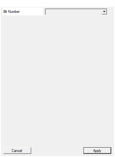
Set the number of bit used in the counter accumulator
Number of bits in the counter.
Available values: 8, 16, 24, 32, 40, 48, 56, 64
Determines:
- Maximum count = 2^BitNumber - 1
- Maximum edges before overflow = 2^BitNumber
- Maximum complete cycles before overflow = 2^(BitNumber-1)
Sizing consideration: Both-edge counting accumulates 2× faster than single-edge. Account for this when sizing:
- If single-edge needs N bits, both-edge needs N+1 bits
- For same measurement duration and input frequency
Example:
- 1 MHz input, 1 second measurement:
- Single-edge: 1M counts → 20 bits
- Both-edges: 2M counts → 21 bits
Default: 32
Options: 8 16 24 32 40 48 56 64
Functional description
The counter implements dual-edge detection by detecting both transitions:
Edge detection mechanism
$$ \text{Rising Edge} = \text{IN}(n) \land \overline{\text{IN}(n-1)} $$
$$ \text{Falling Edge} = \overline{\text{IN}(n)} \land \text{IN}(n-1) $$
$$ \text{Any Edge} = \text{Rising Edge} \lor \text{Falling Edge} = \text{IN}(n) \oplus \text{IN}(n-1) $$
Where:
- IN(n) = Current value of IN signal
- IN(n-1) = Previous value of IN signal
- ⊕ = XOR operation (detects any change)
Counter increments whenever IN changes state (0→1 or 1→0).
Counting comparison
For a 50% duty cycle square wave input:
| Counter Type | Edges Counted | Count per Cycle | Effective Rate |
|---|---|---|---|
| Rising Edge | 0→1 only | 1 | 1× input freq |
| Falling Edge | 1→0 only | 1 | 1× input freq |
| Both Edges | 0→1 and 1→0 | 2 | 2× input freq |
Frequency doubling effect
Both-edge counting effectively doubles the counting rate:
- Input frequency f generates 2f counts per second
- Useful for maximizing resolution in frequency measurement
- Enables counting faster events with slower system clock
Practical example
100 kHz input signal, 1 second measurement window:
- Rising edge counter: 100,000 counts
- Falling edge counter: 100,000 counts
- Both edges counter: 200,000 counts (2× resolution)
Timing diagram
The diagram shows:
- Both rising and falling edges detected
- Counter increments on every edge
- Twice the count rate vs single-edge detection
Typical use cases
- High-resolution frequency measurement: Double the measurement resolution
- Quadrature decoding: Count encoder transitions (with proper quadrature logic)
- Pulse transition counting: Count all state changes
- Maximum throughput counting: Count events at maximum rate
- Toggle detection: Detect and count signal toggles
- Activity monitoring: Count all transitions for activity measurement
Design considerations
When to use Both Edges counter
Advantages:
- 2× counting resolution vs single-edge
- Better frequency measurement accuracy
- Maximum counting throughput
Use Both Edges Counter for:
- Frequency measurement (maximizes resolution)
- Transition counting (both directions significant)
- Activity measurement (total transitions matter)
- Speed measurement (encoder applications)
Use Rising/Falling Edge Counter for:
- Event counting (events marked by specific edge polarity)
- Direction-sensitive counting
- Pulse start/end discrimination
- Standard digital logic interfacing
Input frequency limits
Since each cycle produces 2 counts:
- Maximum effective count rate: CLK_Frequency (not CLK_Freq/2)
- Maximum input frequency: CLK_Frequency / 2
- For 100 MHz clock: Max 50 MHz input → 100 M counts/second
Choosing bit width
Consider 2× count rate when sizing counter:
| Application | Input Freq | Measure Time | Edges/Sec | Min Bits |
|---|---|---|---|---|
| 1 kHz signal, 1s | 1 kHz | 1 s | 2,000 | 11 bits |
| 100 kHz signal, 1s | 100 kHz | 1 s | 200,000 | 18 bits |
| 1 MHz signal, 1s | 1 MHz | 1 s | 2,000,000 | 21 bits |
| 10 MHz signal, 100ms | 10 MHz | 0.1 s | 2,000,000 | 21 bits |
Comparison with single-edge counters
Resource usage:
- Similar to single-edge counters (one additional XOR gate)
- Same number of flip-flops
- Negligible area overhead
Performance:
- Same maximum input frequency (CLK/2)
- Double the counting rate
- Same latency (1-2 cycles)