
RF Multi-stage FIR Decimator
Multi-stage cascade FIR decimator with a fixed rate baked into the netlist. You specify the input and output sample rates, the passband edge and stopband attenuation in engineering units (Hz / dB); the plugin factorises the decimation ratio into up to four cheap stages, designs a Kaiser-window low-pass FIR for each, quantises the coefficients and emits the HLS. Real or complex I/Q, with the input and output format chosen independently. Configured in a custom graphical designer with a live resource estimate.
Introduction
The Multi-stage FIR Decimator turns a high-rate baseband stream into a low-rate one while rejecting everything that would alias into the new band. Doing a large decimation in one FIR is prohibitively expensive; the efficient answer is a cascade of small decimators, each dropping the rate by a modest factor with a relaxed anti-alias filter, so the total tap count (and DSP count) is a fraction of the single-stage design.
You do not enter taps or ratios directly. Instead you give the design intent in physical units:
Input Sample Rate (Hz) e.g. 1 000 000
Output Sample Rate (Hz) e.g. 20 000 -> R = 50
Passband Edge (Hz) e.g. 8 000
Stopband Atten. (dB) e.g. 80
and the plugin does the rest: it factorises R = Fin / Fout into up to
four factors (preferring 5, 3, 2, largest first), designs a Kaiser-window
low-pass FIR per stage (passband = your passband edge, stopband edge = the
new Nyquist after that stage), quantises each to signed CoefSize
integers with unity DC gain, and generates the cascade.
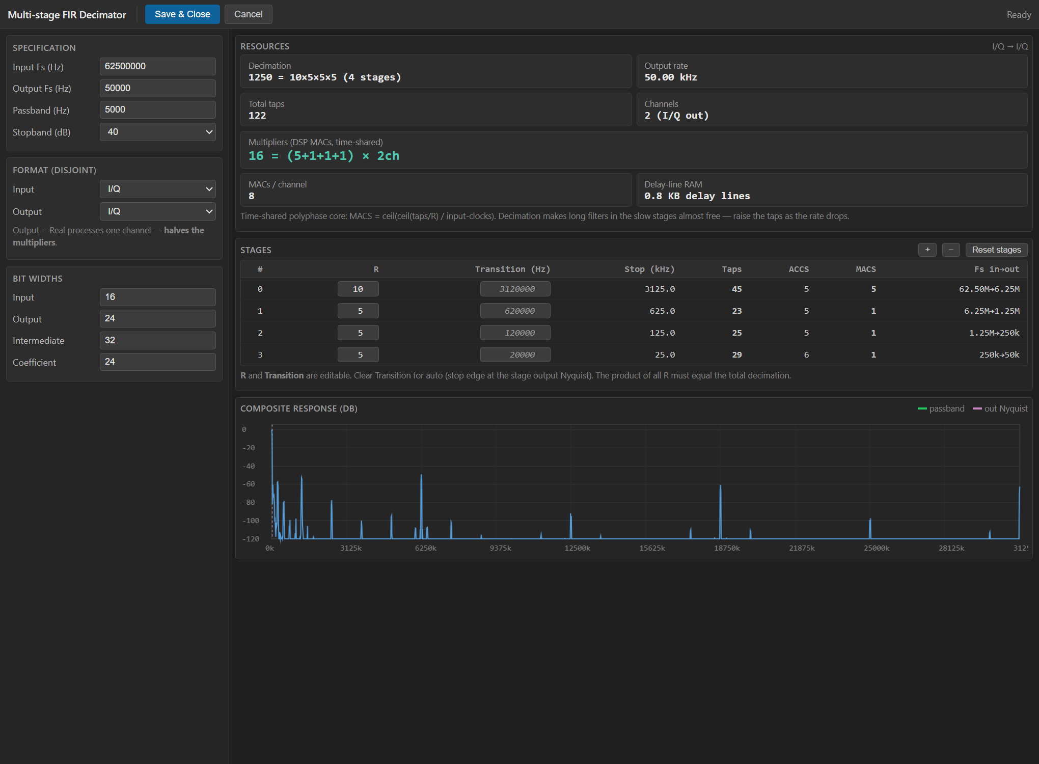
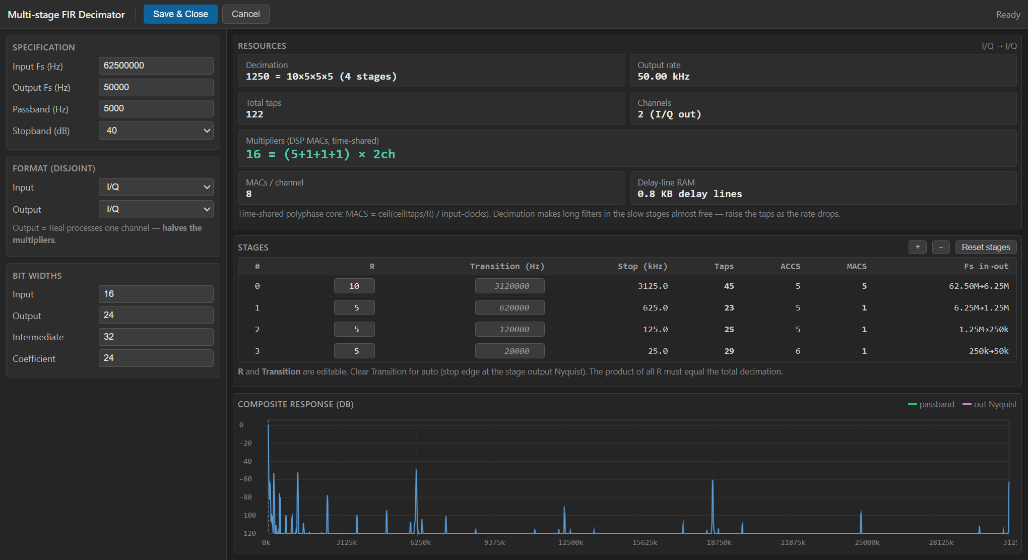
The block uses a custom WebView2 graphical designer instead of the standard property grid. Double-clicking the block opens the designer (shown above), where you set the rates, passband, attenuation and bit widths, pick the input/output format, and read a live resource estimate — the per-stage factorisation, tap counts and multiplier usage — before committing. Properties are set there, not in a plain grid.
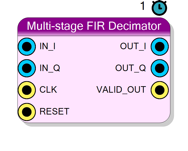
IN_I / IN ─┐ [ stage0: /r0 ]→[ stage1: /r1 ]→ ... → OUT_I / OUT
IN_Q ─┘ (Kaiser LP) (Kaiser LP) └─ OUT_Q
VALID_OUT ── (decimated tick)
Pin Description
OutputFreqHz). Latch the output pins
only when it is high.
VALID_OUT is high.
Properties
Bit width of each I/Q input sample (signed).
Bit width of each signed I/Q input sample. Range 4 to 32, default 16.Default: 16
Options: 4 5 6 7 8 9 10 11 12 13 14 15 16 17 18 19 20 21 22 23 24 25 26 27 28 29 30 31 32
Bit width of each I/Q output sample (signed).
Bit width of each signed I/Q output sample. Range 8 to 40, default 24.Default: 24
Options: 8 9 10 11 12 13 14 15 16 17 18 19 20 21 22 23 24 25 26 27 28 29 30 31 32 33 34 35 36 37 38 39 40
Bit width of the signal between stages (signed).
Bit width of the signal carried between stages (signed). One of 20, 24, 28, 32, 36, 40, 48. Wider preserves more dynamic range through the cascade. Default 32.Default: 32
Options: 20 24 28 32 36 40 48
Bit width of each coefficient (signed). 24 gives ~140 dB dynamic range.
Bit width of each signed coefficient. One of 12, 14, 16, 18, 20, 24. 24 gives ~140 dB coefficient dynamic range. Default 24.Default: 24
Options: 12 14 16 18 20 24
Input sample rate in Hz.
Input sample rate in Hz (text). Default 1000000.Default: 1000000
Output sample rate in Hz. Must divide the input rate.
Output sample rate in Hz (text). Should divide the input rate; a non-integer ratio is rounded (with a warning). Default 20000 (giving R = 50 = 552 for the defaults).Default: 20000
Upper edge of the passband in Hz. Signals within [0, PassbandHz] must be preserved with < 0.5 dB ripple.
Upper edge of the passband in Hz. Signals in[0, PassbandHz] are
preserved with low ripple; the same passband is used for every stage.
Must stay below the final Nyquist OutputFreqHz / 2. Default 8000.
Default: 8000
Minimum stopband attenuation of each stage. Higher = more taps.
Minimum stopband attenuation of each stage (dB). One of 40, 60, 80, 90, 100, 120. Higher = more taps per stage. Default 80.Default: 80
Options: 40 60 80 90 100 120
Real: single input channel (IN). I/Q: two input channels (IN_I/IN_Q).
Real (single input channelIN) or I/Q (two input channels
IN_I/IN_Q). Default I/Q.
Default: I/Q
Options: Real I/Q
Real: one output channel (OUT), half the multipliers. I/Q: two channels (OUT_I/OUT_Q).
Real (single output channelOUT, Q pipeline removed -> half the
multipliers) or I/Q (two output channels OUT_I/OUT_Q). Chosen
independently of InputType. Default I/Q.
Default: I/Q
Options: Real I/Q
Config produced by the Multi-FIR Decimator Designer.
Hidden text property holding the Multi-FIR Decimator Designer output as JSON (thehw block: rates, passband, attenuation, widths and
formats). Never shown in a grid — the block is edited through the
designer. The per-stage Kaiser filters are regenerated from these
values at HDL-generation time.
Usage
Multistage factorisation
Let R = round(Fin / Fout) be the total decimation ratio. Splitting it
into a cascade
R = r0 * r1 * ... * r_{M-1} (M <= 4 stages)
is much cheaper than one big filter, because only the last stage has
to build the final sharp transition; the earlier stages run at higher
rates but only need to reject the (wide) band that will fold into the next
stage’s Nyquist. The plugin factorises R greedily into primes 5, 3,
2 (falling back to any remaining factor), then orders the factors
largest first so the biggest rate drop — with the most relaxed filter
— happens first and the tightest filters run last at the lowest rate where
they cost the fewest multiplies. Up to 4 stages are supported; the
unused stages compile away.
For each stage k the sample rate steps Fk -> Fk / r_k and the plugin
designs a low-pass with:
f_pass = PassbandHz (same for every stage)
f_stop = (Fk / r_k) / 2 (the new Nyquist)
If any stage’s new Nyquist would fall at or below the passband edge the
compile fails, asking you to lower PassbandHz or raise
OutputFreqHz.
Per-stage FIR design (Kaiser window)
Each stage is a windowed-sinc low-pass with a Kaiser window whose beta
and tap count follow the standard Kaiser formulas from the requested
stopband attenuation A (dB) and the transition width Δω (rad):
beta = 0.1102*(A - 8.7) for A > 50
= 0.5842*(A-21)^0.4 + 0.07886*(A-21) for 21 <= A <= 50
= 0 for A < 21
N = ceil( (A - 7.95) / (2.285 * Δω) ) (forced odd, linear phase)
fc = 0.5 * (f_pass + f_stop) / Fk (normalised cutoff)
h[n] = sinc(2*fc*(n - (N-1)/2)) * kaiser(n, beta)
The taps are DC-normalised (sum h = 1), symmetrised to clean up FP
rounding, then quantised to signed CoefSize bits with a scale of
2^(CoefSize-1) - 1. Higher StopbandAttenDB and narrower transitions
produce more taps, so the resource estimate in the designer scales with
both.
Independent input / output type selection
The input and output formats are chosen independently (a “disjoint” choice), which directly trades multipliers:
InputType—Real(single pinIN) orI/Q(two pinsIN_I/IN_Q).OutputType—Real(single pinOUT) orI/Q(two pinsOUT_I/OUT_Q).
OutputType drives how many channels are actually filtered: with
OutputType = Real the entire Q pipeline is compiled away, so a
Real -> Real cascade uses half the multipliers of I/Q -> I/Q.
The meaningful combinations:
InputType OutputType behaviour
--------- ---------- ---------------------------------------------
I/Q I/Q full complex decimation (2x multipliers)
Real Real real-only decimation (1x multipliers)
I/Q Real filter I only; Q is dropped
Real I/Q Q input tied to 0 -> OUT_Q ~ 0 (warns)
The last row emits a compile warning because the Q output is meaningless (there is no Q input to process).
Bit widths
Data is signed two’s complement.
IN/IN_I/IN_Q: signedInputSizebits.- Between stages the signal is carried at
IntermSizebits (each stage right-shifts its accumulator byCoefSize - 1to hold unity DC gain). OUT/OUT_I/OUT_Q: signedOutputSizebits.
Internal accumulators grow to InputSize + CoefSize + 8 (first stage) and
IntermSize + CoefSize + 8 (later stages) to avoid overflow before the
shift.
Visual designer
This block has no plain property grid. Double-clicking it opens the
Multi-FIR Decimator Designer (see the screenshot in the introduction),
where you enter the input/output rates, passband edge, stopband
attenuation and the input/intermediate/output/coefficient bit widths, and
select the input and output formats. The designer shows a live resource
estimate: how R factorises into stages, the tap count per stage, the
total taps and the resulting multiplier count — so you can trade
attenuation, passband and widths against DSP usage before pressing
Save & Close. The chosen values are mirrored back into the hidden
DecimProject property plus the visible hardware properties documented
below, and the actual Kaiser filters are (re)designed at HDL-generation
time from those values.
Streaming model, latency and throughput
#pragma HLS PIPELINE II=1: the cascade accepts one input sample per system clock (ap_none, no input strobe needed — feed it a continuous stream at the input rate).- Each stage keeps a modulo-
r_kcounter and only pushes a new sample into the next stage on its tick, so the effective rate divides down the chain. VALID_OUTpulses for one clock on each valid decimated output sample (rateFout); read the output pins only when it is high.
Reset
RESET (ap_rst) clears every stage’s delay line, counter and output
register.
Typical applications
- Digital down-conversion back-end: decimate a mixed-down baseband from ADC rate to a manageable processing rate.
- Narrowband channelisation with a steep, high-attenuation final filter.
- Real-only rate reduction (
Real -> Real) at half the DSP cost.
Resources & Timing
-
Latency: One cascade fill (sum of the stage delay lines); VALID_OUT marks each valid output
-
Throughput: One input sample per system clock in; one output sample per R clocks out (rate OutputFreqHz)
Implemented with Vitis HLS as up to 4 cascaded parallel FIR decimators
(each fully unrolled, II=1). Total taps and multiplier count depend on
the factorisation of R, the stopband attenuation and the passband — the
designer’s live estimate reflects this. Coefficients are compile-time
constants (Vivado can prune trivial taps). Choosing Output Type = Real
removes the Q pipeline entirely, halving the multipliers versus
I/Q -> I/Q. Modelled on the PolarFire 1 MSps -> 20 kSps decimator
(R = 50 = 552, ~73 / 105 / 131 taps per stage) but fully generic.