
IFFT TM Realtime
TRUE gapless realtime inverse FFT for Time-Multiplexed signals: complex spectrum in, REAL time-domain signal out. Exact dual of FFT TM Realtime: multiplier-free inverse R-point recombination, conjugate twiddles, R parallel Xilinx xfft cores in inverse mode. Sustains R bins in / R samples out per clock continuously. TM factors 2 and 4.
Introduction
The block reconstructs a continuous real time-domain signal from a stream of $N$-point complex spectra ($R$ bins per clock in, $R$ time samples per clock out, no dead cycles). It is the exact inverse of the FFT TM Realtime block and consumes its output format directly: at cycle $k$ input lane $q$ carries bin $k + q \cdot N/R$.
Internally it runs the polyphase split of the forward block backwards:
$$ u_r[k] = \sum_{q=0}^{R-1} W_R^{-rq}, X[k + q\tfrac{N}{R}] = R, W_N^{rk} X_r[k] $$
The inverse $R$-point sum uses only $\pm 1 / \pm j$ (no multipliers), the conjugate twiddle $W_N^{-rk}$ (16-bit ROM, one complex multiplier per lane) removes the phase term, and $R$ Xilinx xfft cores of $N/R$ points - switched to inverse mode at startup through their configuration channel - transform each branch back to time. Output lane $r$ then carries exactly the time samples $n$ with $n \bmod R = r$: the natural TM order.
Only the real part is emitted. The input spectrum is expected to be conjugate-symmetric ($X[N-b] = X^*[b]$, which is automatic if it was produced by an FFT of a real signal); any residual imaginary part is discarded.
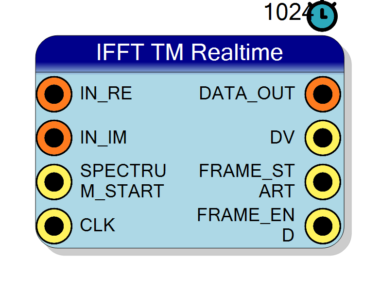
Pin Description
Properties
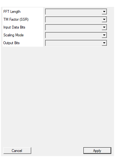
Number of points of the inverse transform (must be power of 2)
Transform length N (64..16384, power of 2). Must match the spectrum source.Default: 1024
Options: 64 128 256 512 1024 2048 4096 8192 16384
Time Multiplexing factor (samples per clock). 2 or 4 (multiplier-free recombination).
TM factor R: 2 or 4 only. These factors keep the recombination stage multiplier-free ($W_R^{-rq} \in {\pm 1, \pm j}$).Default: 4
Options: 2 4
Bit width of each spectrum component RE/IM (8-30 bits, signed)
Spectrum component width RE/IM (8..30, signed).Default: 16
Options: 8 9 10 11 12 13 14 15 16 17 18 19 20 21 22 23 24 25 26 27 28 29 30
No Scaling: full bit growth (InputBits + log2(N) + 1, the output is N*x). Grow to Max: saturated to 27 bits. Scale: output divided by N (true x[n] amplitude), InputBits wide (saturated).
- Scale (default): output divided by N (round half up) - reconstructs the original amplitude when fed by an unscaled FFT.
- No Scaling: output = N*x, full bit growth (saturating, capped at 32).
- Grow to Max: saturated to 27 bits.
Default: Scale
Options: No Scaling Grow to Max Scale
Width of DATA_OUT samples (saturating). Auto: InputBits in Scale mode, InputBits+log2(N)+1 otherwise. Set 16 to get back the original 16-bit signal after an unscaled FFT -> IFFT (Scale) chain.
Width of the DATA_OUT samples (saturating). Auto follows the ScalingMode policy (InputBits wide in Scale mode). Set an explicit value - e.g. 16 after an unscaled FFT of a 16-bit signal - to force the output bus width regardless of InputBits.Default: Auto
Options: Auto 8 9 10 11 12 13 14 15 16 17 18 19 20 21 22 23 24 25 26 27 28 29 30 31 32
Chaining with FFT TM Realtime : the round trip
Connect OUT_RE/OUT_IM of the FFT block to IN_RE/IN_IM and its
FRAME_START to SPECTRUM_START: the alignment is then automatic.
Any frequency-domain processing placed in between (masking, filtering,
per-bin gain) must preserve the lane/bin mapping and the conjugate
symmetry of the spectrum.
To get back the ORIGINAL bit width (e.g. a 16-bit signal in, 16-bit signal out), configure the pair like this:
| Block | FFTLength | InputBits | ScalingMode | Output |
|---|---|---|---|---|
| FFT TM Realtime | N | 16 | No Scaling | 16 + log2(N) + 1 bits (27 for N=1024), full precision |
| IFFT TM Realtime | N | 16 + log2(N) + 1 (27) | Scale + Output Bits = 16 | 16 bits, original amplitude |
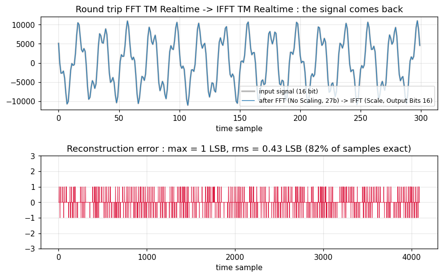
The FFT must stay unscaled (dividing the spectrum by N there would quantize the small bins away); the division by N happens once, at the IFFT output, with round-half-up. Verified in simulation (N=1024, R=4, two tones + noise at 2/3 full scale): reconstruction error max 1 LSB, rms 0.43 LSB, 82% of samples bit-exact, ~1270 clocks total latency:
SPECTRUM_START tells the block which cycle carries bin 0. The first
pulse arms the internal bin counter and the data stream to the xfft
cores; after that the counter free-runs with period $N/R$ and each
further pulse re-checks the alignment. Nothing is emitted before the
first pulse.
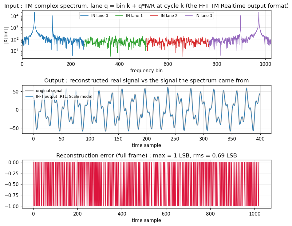
The figure above is real simulation data ($N=1024$, $R=4$, 16-bit spectrum of two tones + noise, Scale mode): the reconstruction matches the original signal within 1 LSB (rms 0.7 LSB, the rounding floor).
How to read the output
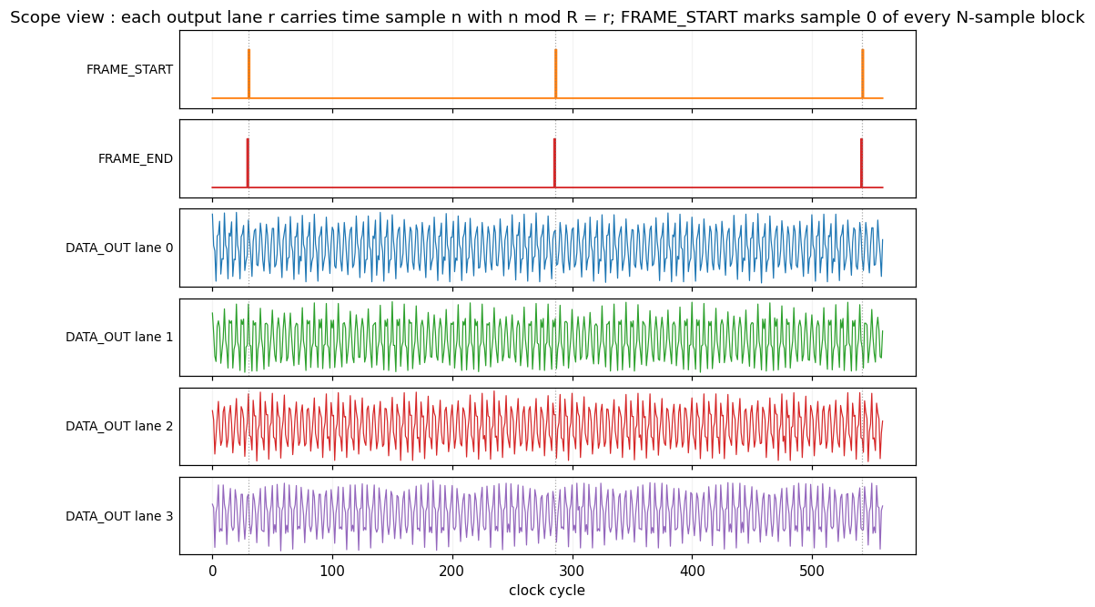
DATA_OUTlane $r$ = time sample $n$ with $n \bmod R = r$; reading the lanes 0..R-1 at one DV cycle gives R consecutive samples.FRAME_STARTpulses on the cycle carrying sample 0 of each reconstructed $N$-sample block,FRAME_ENDon the cycle carrying the last $R$ samples. One block = $N/R$ clock cycles.DVgoes high once the first block emerges and stays high continuously (gapless).
Scaling
The raw chain gain is $N$ (unnormalized inverse transform), mirroring the unscaled forward block:
- Scale (default): output divided by $N$ - if the input is the No Scaling spectrum of a signal $x$, the output is $x$ itself, InputBits wide (saturating).
- No Scaling: full bit growth, output $= N \cdot x$, InputBits + log2(N) + 1 bits (saturating, capped at 32).
- Grow to Max: same arithmetic, saturated to 27 bits.
Latency and resources
- Throughput: R bins in / R samples out every clock, sustained.
- Latency: dominated by the xfft cores (roughly $2 \cdot N/R$ clocks plus pipeline overhead).
- Resources: $R$ xfft cores of $N/R$ points, $R-1$ twiddle ROMs ($N/R \times 32$ bit), $R$ complex multipliers, adders for the recombination. Slightly more than the forward block because the xfft input is InputBits + log2(R) + 1 wide.