DAQ LEMO
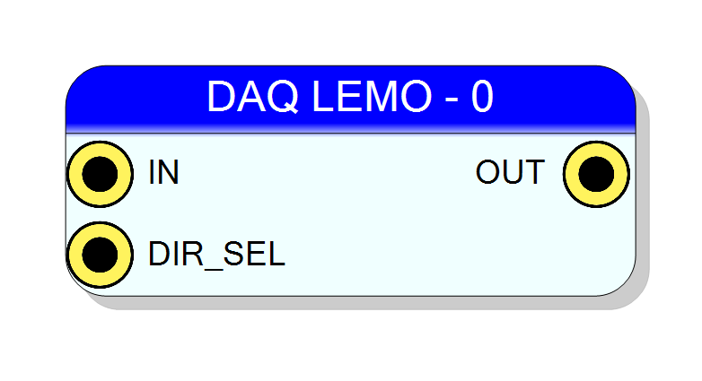
Board-pin block that connects the design to one of the two front-panel LEMO connectors of the NI DAQ121. It has no logic and no HDL of its own: it simply wires IN, OUT and DIR_SEL to the board’s lemo_out, lemo_in and lemo_out_en signals for the connector selected by the Port property.
Introduction
Principle of Operation
The NI DAQ121 carries two general-purpose front-panel LEMO connectors, numbered 0 and 1. Each of them is bidirectional: the FPGA has a separate input pin, output pin and output-enable pin per connector, and the on-board buffer decides which way the line is driven.
One DAQ LEMO block claims exactly one connector, chosen with the Port property
(0 or 1) — the number is drawn in the block caption, DAQ LEMO - 0.
The block is pure interconnect: CompileHDL emits three concurrent VHDL assignments into the
top-level architecture body and nothing else.
DAQ LEMO block board top (top_project_name.vhd)
─────────────────────────────────
your logic ──► IN ──────────────► lemo_out(P) ──► lemo_out_0(P) <= NOT lemo_out(P) ──► LEMO P
your logic ──► DIR_SEL ─────────► lemo_out_en(P) ──► lemo_out_en_0(P) ────────────► buffer dir
your logic ◄── OUT ◄──────────── lemo_in(P) ◄── lemo_in_0(P) ◄────────────────── LEMO P
Mind the naming: from the block’s point of view IN is the signal you feed into the
block and it leaves the board, while OUT is what the block gives out to your design and
it comes from the connector.
Pin Description
lemo_out(<Port>) <= IN;
which the board top inverts before the pad. Left open, nothing is emitted and the block
does not drive the LEMO output at all.
Only meaningful together with DIR_SEL asserted.
lemo_out_en(<Port>). Left open, the compiler emits a hard '0', so the block does not
request the output driver. Drive it with a constant or a register bit to turn the
connector into an output.
OUT <= lemo_in(<Port>);, taken straight from
the FPGA pad with no synchroniser and no inversion. Resynchronise it in your own clock
domain before use. Leaving it unconnected is harmless — no HDL is generated for it.
Properties
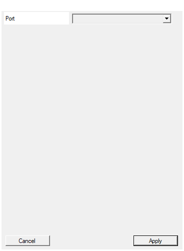
Lemo on the DAQ frontal panel
Which of the two front-panel LEMO connectors this block owns. The value is used verbatim
as the index of lemo_in / lemo_out / lemo_out_en and is shown in the block caption
(DAQ LEMO - 0).
| Value | Connector | lemo_in_0 |
lemo_out_0 |
lemo_out_en_0 |
|---|---|---|---|---|
0 |
LEMO 0 | B14 | H12 | H13 |
1 |
LEMO 1 | F15 | C13 | D14 |
Use each value at most once per design. It can be changed after the block is created and does not rebuild the symbol. Default: 0.
Default: 0
Options: 0 1
⚙️ Detailed Operation
What the compiler emits
CompileHDL registers the three pads with GenerateServiceHDL and then walks the resulting
signal list, writing one line per pin that is actually used (P is the Port value):
| Pin | Condition | VHDL emitted |
|---|---|---|
OUT |
connected | <net>(0) <= lemo_in(P); |
IN |
connected | lemo_out(P) <= <net>(0); |
DIR_SEL |
connected | lemo_out_en(P) <= <net>(0); |
DIR_SEL |
left open | lemo_out_en(P) <= '0'; |
Nothing is emitted for an unconnected IN or OUT, so a block that is only used as an input
leaves lemo_out(P) alone.
The board side
In boards/ni/board_NIDAQ121/support_files/nidaq121_dll/top_project_name.vhd the three
internal buses are 2 bits wide and are wired to the pads as:
lemo_in <= lemo_in_0; -- from the connectors, straight through
lemo_out_0 <= not lemo_out; -- NOTE: inverted on the way out
lemo_out_en_0 <= lemo_out_en;
The FPGA pin assignments (from NIDAQ121_pinout.xdc), all LVCMOS18:
| Signal | Port 0 | Port 1 |
|---|---|---|
lemo_in_0 |
B14 | F15 |
lemo_out_0 |
H12 | C13 |
lemo_out_en_0 |
H13 | D14 |
The board also has a lemo_term_0 pair (K15 / K14) for the input termination. This block
does not drive it — termination is not controllable from the DAQ LEMO symbol.
The logic levels seen at the LEMO connector itself are set by the on-board buffer and are not determined from the sources in this repository; only the 1.8 V FPGA-side standard is.
Direction control
DIR_SEL drives the board’s lemo_out_en(P). With the pin left open the compiler forces it
to '0', i.e. the block does not request the output driver, which is the safe default for
a connector used as an input. Tie DIR_SEL to a constant '1' (or to a register bit) to use
the connector as an output. The electrical polarity of the enable at the buffer is not
established anywhere in this repository — check it once before shipping a design that switches
direction at runtime.
Things that look like features but are not
CompileHDLalso contains a branch for a pin whose name starts withOE, which would writeg_dir_signal(P). There is noOEpin on the symbol, andg_dir_signaldoes not exist in the NIDAQ121 top level — that signal belongs to the V2495 board. The branch is inherited fromSciPlugin_V2495Interfaces/Component_gport.vband never fires.CompileSDKis a stub that returns success; there is noCompileMMC. The block exposes no software registers — if you want to steer the direction from the host, driveDIR_SELfrom a register block.AvailableInSubpageisFalse: the block can only be placed on the top page of a design, not inside a subdesign.- The block is offered only when the project targets the NI DAQ121
(board GUID
10B906F8-657F-4C13-A697-4637BE6DEC27). It needs no license.
Typical uses
- Trigger / veto input — leave
DIR_SELopen, take the pulse onOUT, resynchronise it, and feed it toTRIG_EXTof an acquisition block. - Busy or trigger output — drive
INwith your signal andDIR_SELwith a constant'1'; remember the inversion in the board top. - Runtime-switchable line — drive
DIR_SELfrom a control register so the same connector can be an input during setup and an output during acquisition.
Resources & Timing
-
Latency: 0 — the block is pure wiring, no register is inserted in either direction
-
Throughput: Combinational; the input path is asynchronous to every clock in the design
- No HDL file is written: only three concurrent assignments in the top-level architecture.
- Two LEMO connectors exist, so at most two of these blocks can be placed.
- The board top inverts the outgoing path (
lemo_out_0 <= not lemo_out); the incoming path is not inverted.