
STD Logic Vector / TM Converter
Flexible bidirectional converter between std_logic_vector and time-multiplexed (TM) signal formats. Supports all four conversion modes: STD→STD, STD→TM, TM→STD, and TM→TM. Enforces total bit width equality constraint (input size × input TM factor = output size × output TM factor). Pure combinational logic with zero latency.
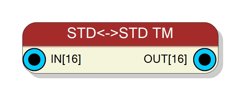
Introduction
This block provides flexible conversion between std_logic_vector and time-multiplexed (TM) signal formats. It supports four conversion modes based on input/output type configuration:
- STD → STD: Direct bit-width conversion (resize)
- STD → TM: Pack scalar signal into TM format
- TM → STD: Unpack TM format to scalar signal
- TM → TM: Repack between different TM factors
The key constraint is total bit width equality: $$ W_\text{in} \times \text{TM}\text{in} = W\text{out} \times \text{TM}_\text{out} $$
The operation is purely combinational with zero clock latency.
Pin Description
Input signal, either std_logic_vector or TM. Type: Configurable via Input data type property
- STD_LOGIC_VECTOR: scalar signal
- STD_LOGIC_VECTOR_TM: TM signal
Width:
- If scalar: Input bits property
- If TM: Input bits × Input Time Multiplexing
Output signal, either std_logic_vector or TM. Type: Configurable via Output data type property
- STD_LOGIC_VECTOR: scalar signal
- STD_LOGIC_VECTOR_TM: TM signal
Width:
- If scalar: Out bits property
- If TM: Out bits × Output Time Multiplexing
Output is combinational (zero latency). Total output bits must equal total input bits.
Properties
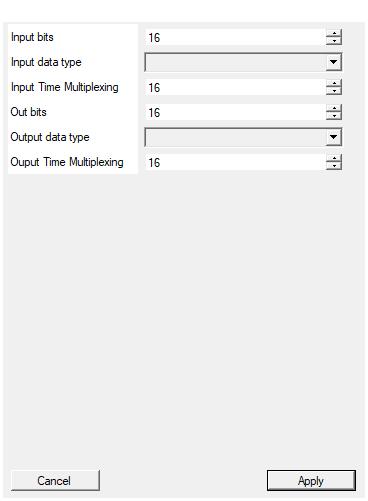
Set the number of bits of the input
Number of bits for input signal (1 to 2048). If input is TM, this is the width per TM phase. If scalar, this is the total width.Default: 16
Range: 1 – 2048
Select the input data type between STD or TM
Input signal type: STD_LOGIC_VECTOR (scalar) or STD_LOGIC_VECTOR_TM (time-multiplexed).Default: STD_LOGIC_VECTOR
Options: STD_LOGIC_VECTOR STD_LOGIC_VECTOR_TM
Set the input time multiplexing
Input time multiplexing factor (1 to 32). Only used if Input data type is STD_LOGIC_VECTOR_TM. For scalar inputs, this value is ignored (effectively 1).Default: 16
Range: 1 – 32
Set the number of bits of the output
Number of bits for output signal (1 to 2048). If output is TM, this is the width per TM phase. If scalar, this is the total width. Must satisfy: Input bits × Input TM = Out bits × Output TM.Default: 16
Range: 1 – 2048
Select the output data type between STD e TM
Output signal type: STD_LOGIC_VECTOR (scalar) or STD_LOGIC_VECTOR_TM (time-multiplexed).Default: STD_LOGIC_VECTOR
Options: STD_LOGIC_VECTOR STD_LOGIC_VECTOR_TM
Set the output time multiplexing
Output time multiplexing factor (1 to 32). Only used if Output data type is STD_LOGIC_VECTOR_TM. For scalar outputs, this value is ignored (effectively 1).Default: 16
Range: 1 – 32
Functional description
This component performs format conversion while preserving the total number of bits. The conversion mode is automatically determined by the input/output type properties.
Bit width constraint
The fundamental requirement is: $$ \text{Total Input Bits} = \text{Total Output Bits} $$
More specifically: $$ W_\text{in} \times F_\text{in} = W_\text{out} \times F_\text{out} $$
where:
- $W_\text{in}$ → Input Size (bits per phase if TM, total if scalar)
- $F_\text{in}$ → Input TM Factor (1 for scalar, 2-32 for TM)
- $W_\text{out}$ → Output Size (bits per phase if TM, total if scalar)
- $F_\text{out}$ → Output TM Factor (1 for scalar, 2-32 for TM)
If this constraint is violated, the component configuration is invalid and compilation will fail.
Conversion Mode 1: STD → STD (Scalar to Scalar)
Direct wire assignment, potentially with bit width change:
- Input: std_logic_vector of width $W_\text{in}$
- Output: std_logic_vector of width $W_\text{out}$
- Constraint: $W_\text{in} = W_\text{out}$ (same total bits)
Example:
- Input: 32-bit scalar → Output: 32-bit scalar (direct wire)
Conversion Mode 2: STD → TM (Scalar to TM)
Partition scalar signal into TM phases:
- Input: std_logic_vector of width $W_\text{in}$
- Output: TM with $F_\text{out}$ phases, each $W_\text{out}$ bits wide
- Constraint: $W_\text{in} = W_\text{out} \times F_\text{out}$
The input is split into consecutive chunks: $$ \text{OUT Phase }i = \text{IN}[(i+1) \times W_\text{out} - 1 : i \times W_\text{out}] $$
Example:
- Input: 64-bit scalar → Output: TM Factor 4 × 16 bits/phase
- IN[15:0] → Phase 0, IN[31:16] → Phase 1, etc.
Conversion Mode 3: TM → STD (TM to Scalar)
Concatenate all TM phases into a single scalar:
- Input: TM with $F_\text{in}$ phases, each $W_\text{in}$ bits wide
- Output: std_logic_vector of width $W_\text{out}$
- Constraint: $W_\text{in} \times F_\text{in} = W_\text{out}$
All TM phases are concatenated: $$ \text{OUT}[(i+1) \times W_\text{in} - 1 : i \times W_\text{in}] = \text{IN Phase }i $$
Example:
- Input: TM Factor 4 × 16 bits/phase → Output: 64-bit scalar
Conversion Mode 4: TM → TM (TM Repacking)
Rearrange TM structure while preserving total bits:
- Input: TM with $F_\text{in}$ phases, each $W_\text{in}$ bits wide
- Output: TM with $F_\text{out}$ phases, each $W_\text{out}$ bits wide
- Constraint: $W_\text{in} \times F_\text{in} = W_\text{out} \times F_\text{out}$
Example:
- Input: TM Factor 4 × 16 bits/phase (64 bits total)
- Output: TM Factor 8 × 8 bits/phase (64 bits total)
- Bit positions preserved, only phase boundaries change
Practical examples
Example 1: 4×16 TM to 2×32 TM
- Input: 4 phases × 16 bits = 64 bits
- Output: 2 phases × 32 bits = 64 bits
- Phase 0 out = Phase 0 in || Phase 1 in
- Phase 1 out = Phase 2 in || Phase 3 in
Example 2: 64-bit scalar to 8×8 TM
- Input: 64-bit std_logic_vector
- Output: 8 phases × 8 bits = 64 bits
- IN[7:0] → Phase 0, IN[15:8] → Phase 1, …, IN[63:56] → Phase 7
Timing
The component is purely combinational with zero latency:
| Property | Latency (clock cycles) |
|---|---|
| STD/TM Converter | 0 |
Output is available immediately in the same clock cycle.
Typical use cases
- Repacking TM data between different TM factors
- Converting scalar wide buses to TM format
- Interfacing components with different TM configurations
- Flattening TM data to scalar for specific operations
Important notes
- Total bit width must match - configuration will be validated
- All conversions are purely structural (bit reordering)
- No data transformation occurs, only format conversion
- Component automatically detects conversion mode from type properties