
A395E - DAC Output Expansion
8-channel 16-bit DAC expansion board for V2495. Provides low-speed analog output channels controlled from FPGA logic.
Introduction
The A395E is a DAC (Digital-to-Analog Converter) expansion board for the V2495 that provides 8 low-speed 16-bit analog output channels.
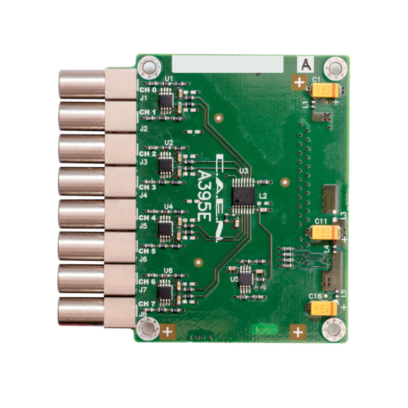
The board can be installed in expansion slots D, E, or F of the V2495 mainboard. The FPGA controls the DAC via a simple write interface.
Product link: CAEN A395E
Pin Description
Properties
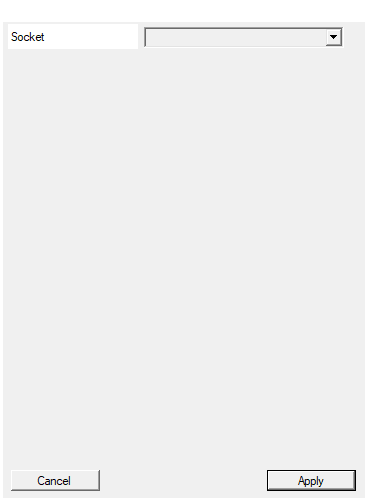
Select the socket hosting the expansion board
Selects the expansion socket where the A395E is installed. Available options: D, E, F. Must match the physical installation location on the V2495 mainboard.Default: D
Options: D E F
Usage
DAC Control Interface
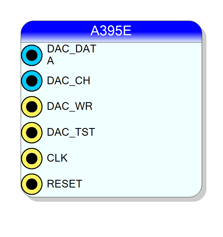
The A395E is controlled through a simple serial-like interface:
┌──────────────────────────────────────────────────────────────────┐
│ A395E DAC Interface │
│ │
│ ┌─────────────┐ ┌─────────────┐ │
│ │ FPGA │═══► DAC_DATA ═══►│ │ │
│ │ Logic │═══► DAC_CH ═════►│ A395E │═══► Analog │
│ │ │═══► DAC_WR ═════►│ (8 ch) │ Outputs │
│ │ │═══► DAC_TST ════►│ │ │
│ └─────────────┘ └─────────────┘ │
└──────────────────────────────────────────────────────────────────┘
Write Sequence
To update a DAC channel:
- Set DAC_DATA to the desired 16-bit value
- Set DAC_CH to the target channel (0-7)
- Pulse DAC_WR HIGH to latch the value
Test Mode
The DAC_TST signal initiates a test procedure for the DAC:
| DAC_TST | Function |
|---|---|
| LOW (0) | Normal operation |
| HIGH (1) | Start DAC test procedure |
Expansion Socket Selection
| Socket | Description |
|---|---|
| D | Expansion slot D |
| E | Expansion slot E |
| F | Expansion slot F |
Signal Characteristics
| Parameter | Value |
|---|---|
| Channels | 8 |
| Resolution | 16 bits |
| Type | Low-speed DAC |
| Interface | Parallel data + channel select + write strobe |
Typical Usage
Use the A395E to generate:
- Threshold voltages for discriminators
- Bias voltages
- Reference levels
- Slow control signals
Resources & Timing
-
Latency: DAC settling time (see A395E datasheet)
-
Throughput: Low-speed updates (not for waveform generation)
- 8 independent 16-bit DAC channels
- Simple parallel interface
- Suitable for threshold/bias generation
Supported Boards
- V2495