

State Machine Editor
How to create and edit finite state machines (‘FSM pages’) in SCI-Compiler: the project tree buttons, the examples gallery, the transition graph, named and prioritized transitions, state body pages with EXIT CONDITION blocks, copy / paste of whole states, and how a machine is placed as a block in a normal diagram.
Introduction
A state machine describes control logic as a set of states and the transitions that move the machine from one state to the next. In SCI-Compiler a state machine is a special page of the project (an FSM page) made of two parts:
- a transition graph: the states, drawn as cards, and the transitions between them, drawn as arrows;
- one body diagram per state: an ordinary SCI-Compiler diagram that describes what the machine drives while it is in that state and when it leaves it.
Inside a body you use the same blocks you use on any other page (logic, comparators, timers, counters, memories…) plus a few blocks that exist only in state machines: State Ports, EXIT CONDITION, STATE ACTIVE / STATE ENTERED and State Variables (see State Bodies, Ports and Variables).
The machine is then placed in any normal diagram as one block, like a sub-design.
This chapter documents the new state machine editor. Projects made with the older editor (Select State Machine block,
state_machinefamily) still open and compile, but new machines are created with the editor described here.
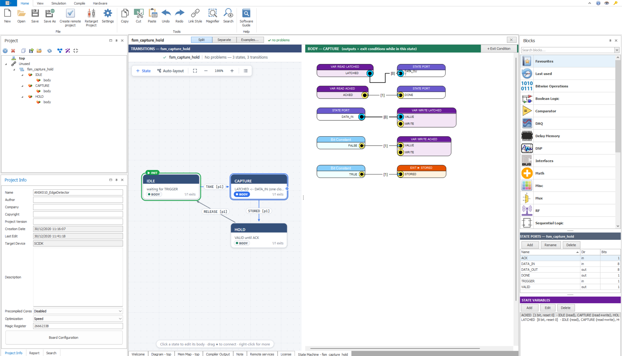
Figure 1: the state machine editor. Left: project tree with the machines and their states. Centre: the transition graph (TRANSITIONS) and the body of the selected state (BODY — CAPTURE). Right: the block palette, with the STATE PORTS and STATE VARIABLES panels of the machine below it.
Creating a State Machine
From the project tree toolbar
The toolbar of the Project panel has three state machine buttons on its right end:
| Button | Action |
|---|---|
| New State Machine | Asks for a name and creates an empty machine with one state, IDLE, which is also the initial state. |
| New State Machine from template… | Opens the examples gallery: pick one of the ready-made machines, choose its name and click Create (see State Machine Examples). |
| Collapse / Expand State Machines | Hides (or shows again) the state pages of every machine in the tree, leaving only the machine nodes. Enabled when the project has at least one machine. |
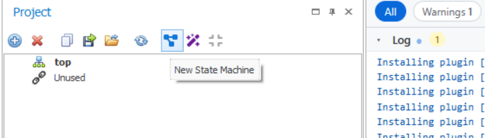
Figure 2: the state machine buttons of the project tree toolbar
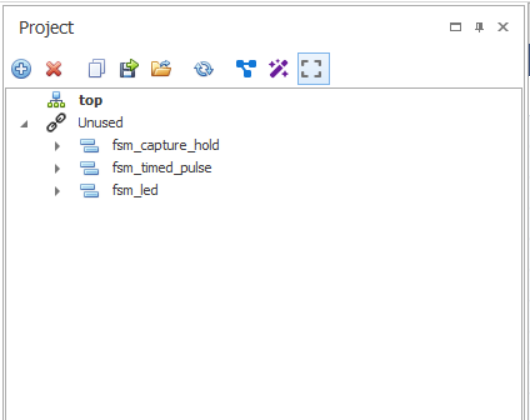
Figure 3: the tree with the state machines collapsed
From the tree context menu
Right-click the Unused folder or the top node: the menu offers Add State Machine and Add State Machine from Example…. Right-click a machine node to get Open Editor, Rename and Delete.
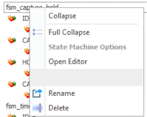
Figure 4: context menu of a state machine node
A new machine appears in the tree under Unused with one child node per state, and under each state its body page. Double-click the machine node (or use Open Editor) to open it.
Machine names follow the usual page-name rules; the generated VHDL entity is called
FSM_<name>. A machine cannot be deleted while it is placed in a diagram.
The Editor Layout
The machine opens in its own central tab, State Machine - <name>. The header strip contains:
- the machine name;
- Split / Separate: Split (default) shows the transition graph and the body of the selected state side by side, with a draggable divider; Separate moves the body editor into a second tab, State Editor - <name>, so that both get the whole width;
- Examples…: opens the examples gallery and creates a new machine from it;
- the validation summary (green no problems, or the red list of problems);
- ✕ closes the editor tab.
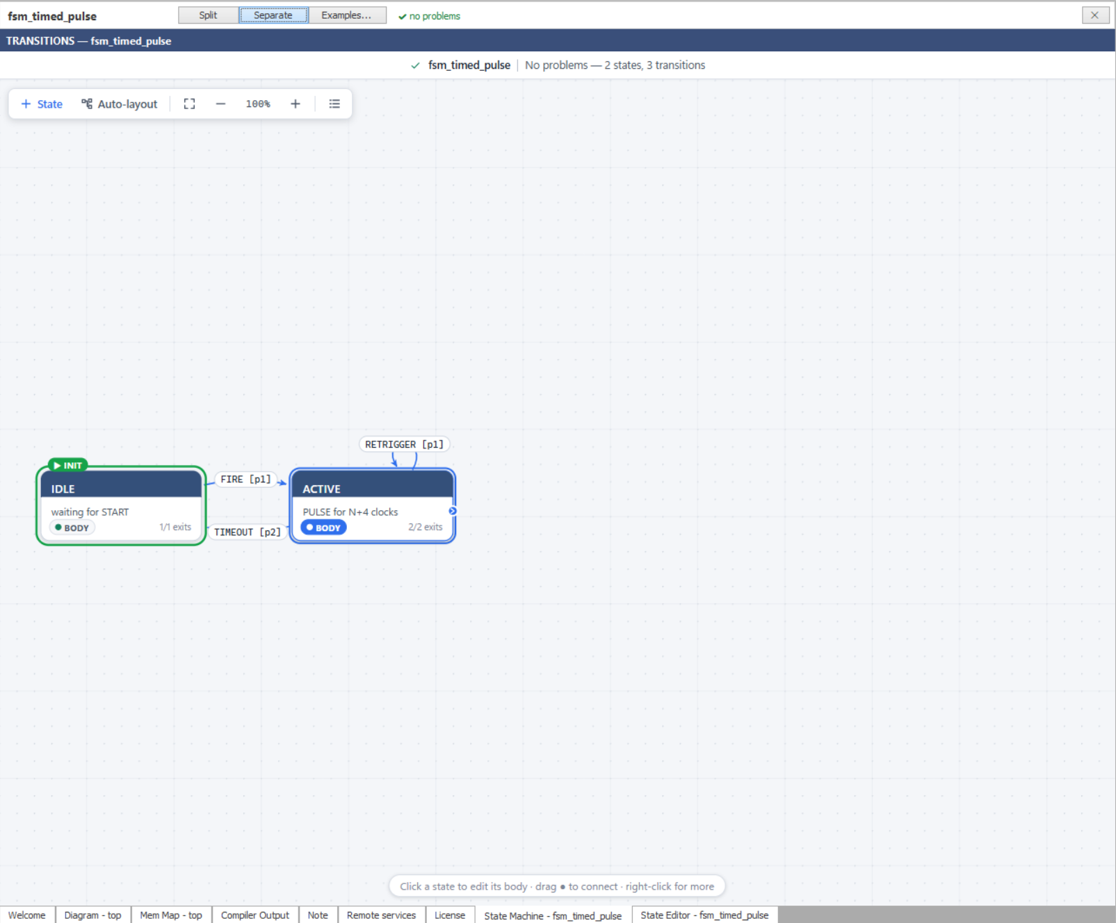
Figure 5: Separate mode: the graph takes the whole tab, the body has its own “State Editor” tab
The right half (or the State Editor tab) shows the body of the state selected in the graph. Its caption reads BODY — <state> (outputs + exit conditions while in this state); until a state is selected it shows select a state in the transition graph.
The Transition Graph
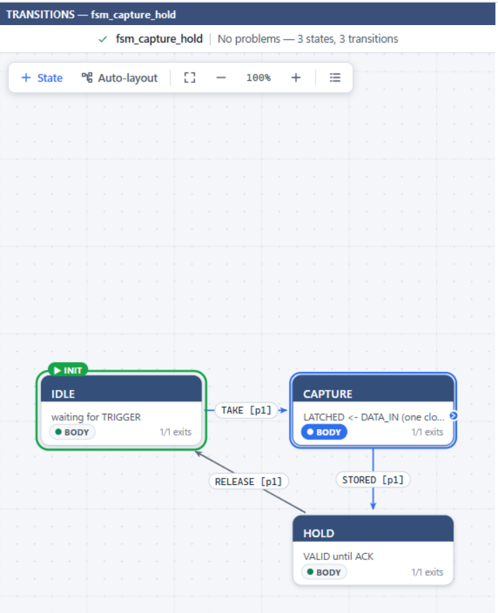
Figure 6: the transition graph of the “Capture and hold” example
Toolbar and navigation
| Control | Function |
|---|---|
| + State | Adds a state (asks for its name). Double-clicking the empty canvas does the same at that point. |
| Auto-layout | Arranges the states in layers starting from the initial state. |
| Fit to view (F) | Zooms and pans so that every state is visible. |
| − / + / percentage | Zoom out, zoom in, reset to 100 %. The mouse wheel zooms, dragging the background pans. |
| Legend | Shows the meaning of badges and colours. |
The line above the canvas summarizes the machine (No problems — 3 states, 3 transitions) or lists its problems; click a problem to select the state or the transition it refers to.
State cards
Each state is a card with its name, an optional comment, the BODY chip and an exit counter:
- ▶ INIT marks the initial (reset) state; it has a green ring.
- n/m exits: m outgoing transitions, n of which already have their EXIT CONDITION block in the body (shown in orange while incomplete).
- terminal: the state has no outgoing transition; it can only be left with RESET. This is legal.
- k unbound: the body contains EXIT CONDITION blocks not bound to any transition (typically after a paste, see below); a red ! badge marks states with problems.
Click a card to select it and load its body on the right. Double-click (or F2) renames it. Drag a card to move it. Right-click opens the state menu:
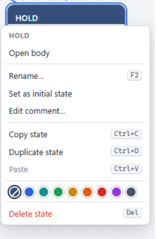
Figure 7: state context menu
- Open body, Rename… (F2), Set as initial state, Edit comment…
- Copy state (Ctrl+C), Duplicate state (Ctrl+D), Paste (Ctrl+V)
- a colour palette for the card
- Delete state (Del): asks for confirmation and deletes the state, its body page, its transitions and the EXIT CONDITION blocks of the transitions entering it.
Ctrl+click or Shift+click selects several states; copy, duplicate and delete then act on the whole group. Right-click on the empty canvas gives Add state here, Paste here, Auto-layout and Fit to view.
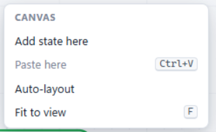
Figure 8: canvas context menu
Transitions (links)
To create a transition, hover a state: a small ● handle appears on the right edge of the card. Drag it onto the destination state (or back onto the same state for a self-loop).
Every transition has:
- a Name: by default
<FROM>_<TO>(for exampleIDLE_ON), made unique with_2,_3… when two transitions join the same states. The name is shown on the arrow and is the name of the EXIT CONDITION block that fires it. - a Priority: an integer, unique among the transitions leaving the same state.
Lower numbers are tested first. The arrow label shows it as
[p1],[p2]…
Click the label of a transition to open its properties: edit Name and Priority and press Apply (Enter). Renaming a transition also renames its EXIT CONDITION block in the body. Body jumps to the body of the source state, Delete removes the transition together with its EXIT CONDITION block.
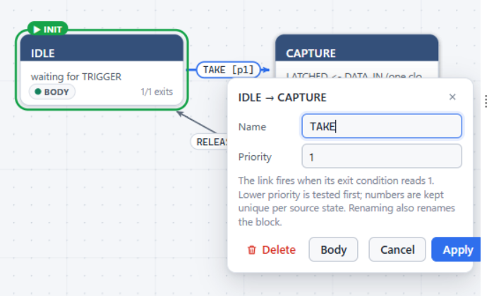
Figure 9: transition properties: name and priority
Right-click a transition for Link properties (name / priority)…, Open body of <source> and Delete transition (Del).
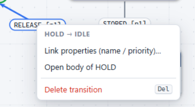
Figure 10: transition context menu
A transition whose source body has no EXIT CONDITION block yet is drawn red and dashed, and the machine reports a problem until the block is placed and wired.
Leaving a State: EXIT CONDITION blocks
A transition is taken when its EXIT CONDITION block, placed in the body of the source state, reads 1:
- the block has one 1-bit input and is captioned
EXIT ► <transition name>(orange header); - wire to it any 1-bit signal computed in the body: a State Port input, a comparator output, a timer flag, a logic expression…;
- a constant 1 (Bit Constant TRUE) makes the transition unconditional: the machine stays in the state for exactly one clock;
- when several EXIT CONDITIONs of the current state read 1 in the same clock, the transition with the lowest priority number wins; when none reads 1 the machine stays where it is.
Placing an EXIT CONDITION:
- the + Exit Condition button in the body caption,
- the palette row Exit Condition (state transition),
- canvas right-click Exit Condition….
All three open a chooser with the outgoing transitions of the state that do not have a block yet:
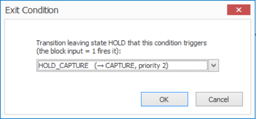
Figure 11: choosing the transition an EXIT CONDITION block fires
Double-click a placed EXIT CONDITION to rebind it to another free transition of the same state. Every transition needs exactly one block, wired, in its source body.
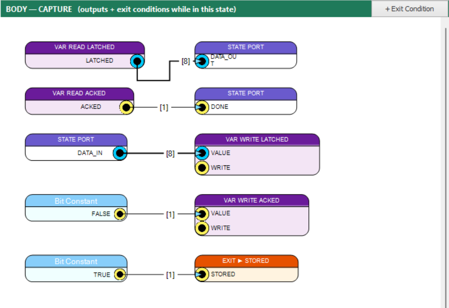
Figure 12: body of state CAPTURE. EXIT ► STORED is wired to a constant TRUE, so the machine stays in CAPTURE for one clock. The other blocks are State Ports and State Variables
Copy, Paste and Duplicate of States
Copy state / Paste and Duplicate state copy whole states, body included, inside the same machine, into another machine, or into another project open in the same SCI-Compiler session.
- The copy is named
<NAME>_COPY(_COPY_2, …), is never the initial state and is placed next to the original (or at the mouse for Paste here). - Transitions are never copied: the pasted state has no incoming or outgoing transition, not even a self-loop. Draw the links again.
- The EXIT CONDITION blocks of the copied body stay in place, still wired, but become
unbound: crimson header, caption
EXIT ► (unbound), cell<old name>?. The machine reports “exit condition … is not bound to any transition” until each of them is rebound (double-click it after drawing the new transition) or deleted. - The State Ports and State Variables used by the body are declared in the destination machine when missing; a paste that would clash with an existing port or variable of another width / direction is refused as a whole.

Figure 13: an EXIT CONDITION copied with its state, waiting to be rebound
Inside a body, blocks are copied and pasted with the normal diagram commands (Ctrl+C / Ctrl+V, also between two different states and between a state and a normal page).
Using the Machine in a Design
On a normal page (top or sub-design) place the machine with the palette row State Machine (new) (category Sub-design, or search “State Machine”). A dialog lists the machines of the project and the instance designator; From example… creates a new machine from the gallery first.
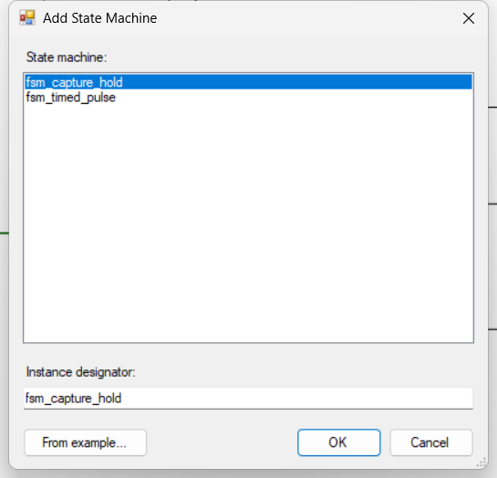
Figure 14: choosing the machine to place
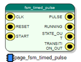
Figure 15: a state machine block on the top page
The block pins are, in order:
| Pin | Direction | Meaning |
|---|---|---|
CLK |
in | Machine clock. Unconnected: the default design clock. |
RESET |
in | Synchronous reset, active high. Unconnected: the global reset. |
| inputs | in | One pin per input State Port of the machine. |
| outputs | out | One pin per output State Port of the machine. |
STATE_OUT |
out | Current state, binary-encoded in the order the states were created (first state = 0); max(1, ceil(log2(N))) bits. |
TRANSITION_OUT |
out | 1 during the first clock spent in a new state (a pulse on every state change). |
Every input pin other than CLK and RESET must be connected. If you add, remove or
resize State Ports (or add states, which may widen STATE_OUT) after placing the block,
compile stops with “Update the state machine block on the parent page so that its pins
match the state machine ports”: delete the block, place it again and reconnect it.
Double-click the block to open the machine in the editor.
Related Documentation
- State Bodies, Ports and Variables
- Generated HDL, Validation and Limitations
- State Machine Examples
- Tutorial: your first state machine
- Tree Menu