Keyboard Shortcuts
Complete reference for SCI-Compiler keyboard shortcuts and advanced wiring techniques. Master selection, editing, zooming, and powerful connection shortcuts (Alt+R, Alt+E, Alt+F, Alt+S, Alt+D) to dramatically accelerate firmware design workflow and productivity.
Introduction
SCI-Compiler provides extensive keyboard shortcuts that dramatically reduce the time required to design FPGA firmware. Mastering these shortcuts transforms diagram editing from a slow, mouse-heavy process into a fast, efficient workflow.
Shortcut Categories
- Standard editing - Copy, paste, undo, redo
- Selection - Multi-select blocks and wires
- Zoom and navigation - View control
- Wiring automation - Advanced connection shortcuts
- Block manipulation - Rotate, arrange
Standard Editing Shortcuts
Common clipboard and editing operations:
| Shortcut | Function | Alternative |
|---|---|---|
| Ctrl+C | Copy selected blocks/wires | Toolbar: Copy button |
| Ctrl+X | Cut selected blocks/wires | Toolbar: Cut button |
| Ctrl+V | Paste from clipboard | Toolbar: Paste button |
| Delete or Canc | Delete selected items | Right-click → Delete |
| Ctrl+Z | Undo last action | Toolbar: Undo button |
| Ctrl+Shift+Z or Ctrl+Y | Redo undone action | Toolbar: Redo button |
Selection Methods
Single selection:
- Click on block or wire
Multiple selection - Drag area:
- Click and hold left mouse button on empty space
- Drag to create selection rectangle
- Release to select all enclosed items
Multiple selection - Ctrl+Click:
- Hold Ctrl key
- Click individual blocks/wires to add to selection
- Click selected items again to deselect
Select all:
- Ctrl+A - Select all blocks and wires in diagram
Zoom and Navigation Shortcuts
Control diagram view efficiently:
| Shortcut | Function |
|---|---|
| Q or - (minus) | Zoom out |
| W or + (plus) | Zoom in |
| Mouse Wheel | Zoom in/out (scroll up/down) |
| A | Zoom to fit (show entire design) |
| B | Zoom to selected block (center and focus) |
| Alt+Drag | Pan diagram (move view) |
Navigation Best Practices
Exploring large designs:
- Press A to see full overview
- Click area of interest
- Press B to zoom to selection
- Use mouse wheel for fine zoom adjustment
- Alt+Drag to pan around
Working on specific area:
- Select relevant blocks
- Press B to center view
- Zoom in with W or mouse wheel
- Work efficiently in focused view
Advanced Wiring Shortcuts
These powerful shortcuts automate complex connection patterns, saving hours of manual wiring.
P - Quick Variable/Register/Port Access
Fast in-place creation of connection points.
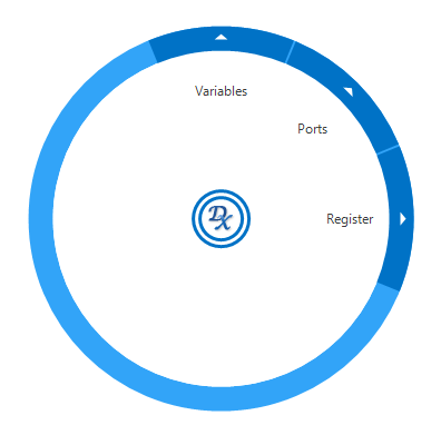
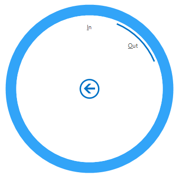
Figure 1: Quick access menu for variables, registers, and ports
Function: Opens context menu for creating:
- Variables - Named connection points
- Registers - Memory-mapped registers
- Ports - Board I/O pins
Usage:
- Press P key in diagram
- Menu appears at cursor
- Select variable/register/port type
- Item created in-place
- Connect immediately
Benefits:
- Faster than toolbar navigation
- Creates at exact cursor position
- Minimal interruption to workflow
Alt+V - Multiply Registers
Automatically create multiple registers from a template.
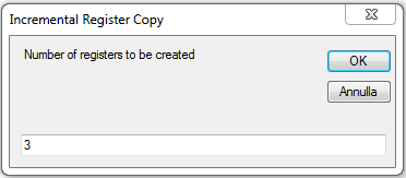
Figure 2: Creating multiple registers with auto-increment
Function: Creates N register blocks with auto-incremented names.
Requirements:
- One or more register blocks selected
- Register names should end with number (e.g., “reg_0”) for proper increment
Usage:
- Select register block(s)
- Press Alt+V
- Dialog appears: “How many registers?”
- Enter number (e.g., 15)
- Click OK
Naming logic:
| Original Name | Generated Names |
|---|---|
reg |
reg_1, reg_2, reg_3, … |
threshold_0 |
threshold_1, threshold_2, threshold_3, … |
baseline_5 |
baseline_6, baseline_7, baseline_8, … |
Multiple selections:
- If multiple registers selected, process runs independently for each
- Each creates its own series of incremented registers
Alt+S - Serial Register Connection
Connect incrementing registers to series of identical blocks.
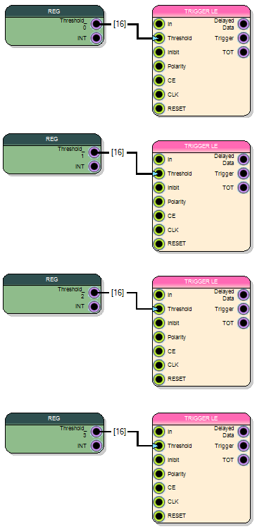
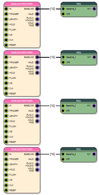
Figure 3: Serial connection from registers to processing blocks
Function: Auto-connect register_N, register_N+1, register_N+2… to multiple block instances.
Requirements:
- Connection to/from register with numeric suffix (e.g., “Threshold_0”)
- Multiple instances of same block type
Usage - Register to Block:
- Create connection:
Threshold_0→Leading Edge Trigger - Select the wire
- Press Alt+S
- Wire turns pink (active mode)
- Click next
Leading Edge Triggerblock - New wire created:
Threshold_1→ clicked block - Repeat clicking more blocks
- Press Esc to exit mode
Usage - Block to Register:
- Create connection:
Baseline Restorer→Baseline_0 - Select the wire
- Press Alt+S
- Wire turns pink
- Click next
Baseline Restorerblock - New wire created: clicked block →
Baseline_1 - Repeat for more blocks
- Press Esc to exit
Use cases:
- Configure 16 identical processing channels
- Each channel has its own threshold register
- Connect
threshold_0throughthreshold_15efficiently
Alt+E - Fan-out to Multiple Blocks
Connect one source to same input pin on multiple destination blocks.
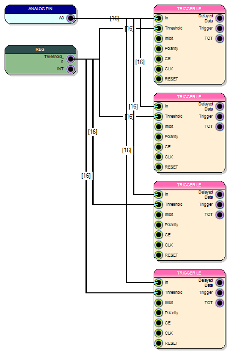
Figure 4: Fan-out from single source to multiple destinations
Function: One output connects to same input pin on N identical blocks.
Usage:
- Create connection:
REG_0→Leading Edge Trigger(Threshold input) - Select the wire
- Press Alt+E
- Wire turns pink
- Click another
Leading Edge Triggerblock - New wire created:
REG_0→ clicked block (Threshold input) - Repeat clicking more blocks
- Press Esc to exit mode
Common scenarios:
Shared configuration:
- One threshold register to all 16 channels
- Global enable signal to multiple blocks
- Common clock to processing chain
Broadcast signals:
- Trigger to multiple DAQ blocks
- Reset to all counters
- Gate to parallel processing paths
Alt+D - Sequential Channel Assignment
Connect multiple sources to incrementing channels of multi-input block.
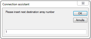
Figure 5: Channel assignment dialog
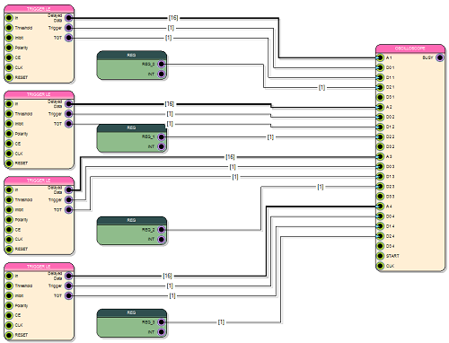
Figure 6: Multiple sources connected to sequential oscilloscope channels
Function: Auto-connect identical blocks to sequential channels (D00, D01, D02…).
Supported multi-channel blocks:
- Digitizer - Multiple data channels
- Oscilloscope - Multiple trace inputs
- Spectrum - Multiple input channels
- Imaging Module - Multi-channel imaging
- Multi-input gates - AND, OR, XOR, Mux, Adder, etc.
Usage:
- Create connection:
Trigger_0→Oscilloscope(D00 channel) - Select the wire
- Press Alt+D
- Dialog appears: “Enter channel index”
- Enter starting index (e.g., 1 for D01)
- Click OK
- Wire turns pink
- Click next source block (
Trigger_1) - New wire created:
Trigger_1→ Oscilloscope (D01) - Click
Trigger_2→ connects to D02 - Continue for all channels
- Press Esc to exit
Channel index:
- Zero-based (0 = first channel)
- Increments automatically for each connection
Use case - 16-channel oscilloscope:
- Connect
Trigger_0→ Oscilloscope D00 - Alt+D → Enter 1
- Click
Trigger_1throughTrigger_15 - All 16 channels connected in seconds!
Alt+R - Replicate Sequential Connections
Auto-create N connections between sequential pins.
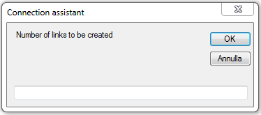
Figure 7: Specify number of connections to replicate
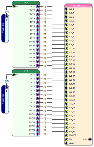
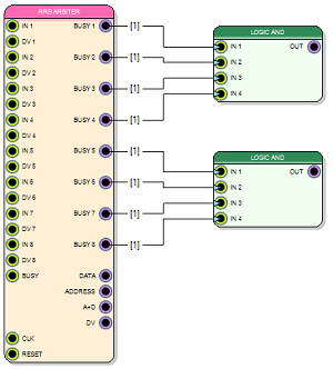
Figure 8: Replicated connections between sequential pins
Function: Create N identical connections between adjacent pins.
Usage:
- Create connection:
Wire Split[0]→Logic Analyzer[0] - Select the wire
- Press Alt+R
- Dialog appears: “Number of links to create”
- Enter number (e.g., 15)
- Click OK
- 15 additional connections created:
Wire Split[1]→Logic Analyzer[1]Wire Split[2]→Logic Analyzer[2]- …
Wire Split[15]→Logic Analyzer[15]
Requirements:
- Source block has multiple sequential outputs (e.g., [0], [1], [2]…)
- Destination block has multiple sequential inputs
- Both blocks have enough pins for N connections
Classic use case - Wire Split to Logic Analyzer:
- Split 16-bit bus into 16 individual signals
- Connect all 16 to Logic Analyzer channels
- One connection + Alt+R with 15 = Done!
Escape to deselect:
- Press Esc to deselect wire and end replication mode
Alt+F - Fan-out Sequential Outputs
Connect sequential outputs from one block to same input on multiple blocks.
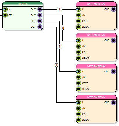
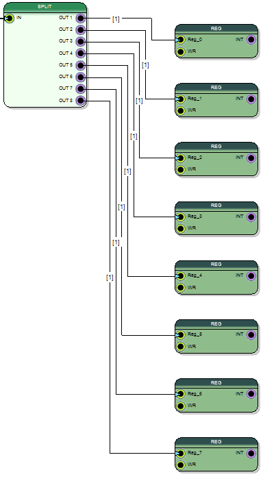
Figure 9: Sequential fan-out from one source to multiple destinations
Function: Output[N], Output[N+1], Output[N+2]… → Same input pin on multiple blocks.
Usage:
- Create connection:
Counter[0]→Register_0 - Select the wire
- Press Alt+F
- Wire turns pink
- Click
Register_1 - New wire created:
Counter[1]→Register_1 - Click
Register_2 - New wire created:
Counter[2]→Register_2 - Continue for all registers
- Press Esc to exit
Supported destinations:
- Register blocks
- Output signal blocks
- Variable blocks
- Identical block instances
Use case - Multi-channel counter readout:
- 16 counters with sequential Counts outputs
- 16 register blocks for readout
- Connect Counts[0]→reg_0, then Alt+F click remaining 15 registers
- All connections created instantly
Block Manipulation Shortcuts
Transform and organize blocks efficiently:
| Shortcut | Function |
|---|---|
| Spacebar | Rotate selected blocks 90° clockwise |
| R | Rearrange wires for optimal visualization |
Spacebar - Rotate Blocks
Function: Rotate selected blocks 90° clockwise.
Usage:
- Select one or more blocks
- Press Spacebar
- Blocks rotate 90° clockwise
- Repeat for 180°, 270°, or back to 0°
Why rotate:
- Optimize signal flow direction (left→right, top→bottom)
- Reduce wire crossings
- Improve diagram readability
- Fit blocks in tight spaces
R - Rearrange Wires
Function: Automatically optimize wire routing.
Usage:
- Select wires to rearrange (or Ctrl+A for all)
- Press R
- Wires automatically re-routed for clarity
Benefits:
- Reduces wire crossings
- Creates cleaner right-angle paths
- Improves visual organization
- Makes diagram more professional
Shortcut Combinations
Combine shortcuts for maximum efficiency.
Multi-Channel Design Workflow
Creating 16-channel signal processing system:
1. Add first processing block
2. Alt+V → Create 16 registers (threshold_0...threshold_15)
3. Connect threshold_0 → block
4. Alt+S → Click 15 more blocks (auto-connect incrementing registers)
5. Add output register
6. Alt+V → Create 16 output registers
7. Connect first block → output_0
8. Alt+S → Click 15 more blocks
9. Alt+F → Connect all outputs to USB endpoint
10. Press A to zoom out and view complete design
Result: 16 identical channels with unique registers in under 2 minutes!
Bus Manipulation Workflow
Processing 32-bit parallel bus:
1. Add Wire Split (32 outputs)
2. Add Logic Analyzer (32 channels)
3. Connect Split[0] → Analyzer[0]
4. Alt+R → Enter 31 → All 32 connections created
5. Select connections
6. Press R → Wires rearranged neatly
Result: Perfect 32-bit bus to analyzer connection in 10 seconds!
Replication Workflow
Copy proven design to all channels:
1. Design single-channel processing (trigger + filter + QDC)
2. Select all blocks (Ctrl+A or drag-select)
3. Ctrl+C to copy
4. Ctrl+V to paste → 15 times
5. Arrange pasted groups vertically
6. Alt+V on each register to increment names
7. Connect inputs with Alt+E
8. Connect outputs with Alt+F
Result: 16-channel processing from 1-channel template in minutes!
Shortcut Reference Table
Complete quick reference for all shortcuts:
Editing & Selection
| Shortcut | Function |
|---|---|
| Ctrl+C | Copy |
| Ctrl+X | Cut |
| Ctrl+V | Paste |
| Ctrl+A | Select All |
| Delete / Canc | Delete selected |
| Ctrl+Z | Undo |
| Ctrl+Shift+Z / Ctrl+Y | Redo |
Zoom & Navigation
| Shortcut | Function |
|---|---|
| Q / - | Zoom out |
| W / + | Zoom in |
| Mouse Wheel | Zoom in/out |
| A | Zoom to fit all |
| B | Zoom to selected |
| Alt+Drag | Pan view |
Advanced Wiring
| Shortcut | Function |
|---|---|
| P | Quick variable/register/port menu |
| Alt+V | Multiply registers |
| Alt+S | Serial register connection |
| Alt+E | Fan-out to multiple blocks |
| Alt+D | Sequential channel assignment |
| Alt+R | Replicate sequential connections |
| Alt+F | Fan-out sequential outputs |
| Esc | Exit wiring mode |
Block Manipulation
| Shortcut | Function |
|---|---|
| Spacebar | Rotate 90° clockwise |
| R | Rearrange wires |
Best Practices
Learning Shortcuts
Beginner approach:
- Start with standard editing (Ctrl+C/V/Z)
- Learn zoom (Q/W/A/B)
- Add one wiring shortcut per week
- Practice on example projects
Progressive mastery:
- Week 1: Ctrl+C/V/Z, Q/W/A/B
- Week 2: Alt+R (most useful!)
- Week 3: Alt+E (fan-out)
- Week 4: Alt+F (sequential fan-out)
- Week 5: Alt+S (register series)
- Week 6: Alt+D (channel assignment)
- Week 7: Alt+V, P, Spacebar, R
Efficiency Tips
- Muscle memory - Practice shortcuts until automatic
- Pink wire - Remember pink = active shortcut mode
- Esc to exit - Always press Esc when done
- Preview first - Create one connection to verify, then use shortcut
- Combine shortcuts - Chain multiple shortcuts in workflow
Common Mistakes
Wrong selection:
- Shortcut requires specific selection (e.g., Alt+S needs register connection)
- Solution: Read “Requirements” for each shortcut
Forgot to press Esc:
- Wire stays pink, interferes with other operations
- Solution: Always press Esc after shortcut operation
Wrong block types:
- Alt+E clicking non-matching block types
- Solution: Ensure destination blocks are identical type
Not enough pins:
- Alt+R requesting more connections than pins available
- Solution: Check source/destination pin counts
Troubleshooting
Shortcut Doesn’t Work
Problem: Pressing shortcut does nothing
Solutions:
- Verify correct selection (wire/block as required)
- Check focus is in Diagram tab (not Editor or Output)
- Ensure no modal dialog is open
- Try clicking diagram first to focus
Wire Doesn’t Turn Pink
Problem: Alt+[key] doesn’t activate mode
Solutions:
- Verify wire is selected (highlighted)
- Check wire meets requirements (e.g., Alt+S needs register)
- Ensure Alt key is pressed while pressing letter
- Try selecting wire again
Wrong Connections Created
Problem: Shortcut creates unexpected connections
Solutions:
- Verify block types match expectations
- Check pin names are identical
- Review connection logic for that shortcut
- Undo (Ctrl+Z) and try again carefully
Can’t Exit Shortcut Mode
Problem: Wire stays pink, can’t work normally
Solutions:
- Press Esc key
- Click empty diagram space
- Select different item
- Restart SCI-Compiler if stuck
Summary
Keyboard shortcuts are essential for efficient SCI-Compiler workflow:
| Category | Key Shortcuts | Impact |
|---|---|---|
| Editing | Ctrl+C/V/Z | Standard productivity |
| Navigation | Q/W/A/B | Fast diagram exploration |
| Wiring | Alt+R/E/F/S/D | 10-100x faster connections |
| Manipulation | Spacebar, R | Cleaner diagrams |
Most impactful shortcuts:
- Alt+R - Replicate connections (saves hours on buses)
- Alt+E - Fan-out (common configurations)
- A - Zoom to fit (orientation)
- Ctrl+Z - Undo (fix mistakes)
- Alt+F - Sequential fan-out (multi-channel)
Time savings:
- Manual wiring 16-channel design: 2-3 hours
- With shortcuts: 10-15 minutes
- Efficiency gain: 10-20x faster!
Practice makes perfect:
- Shortcuts feel awkward initially
- Become natural with repetition
- Essential for professional productivity
- Transform firmware design experience
Master these shortcuts to become a SCI-Compiler power user!