
X2751 List (DPP)
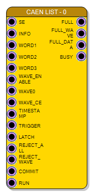
List-mode data acquisition block for the X2751 board. Transfers events with parameters and optional waveforms to the PC via CAEN FELib.
Introduction
The X2751 List block (also called DPP - Digital Pulse Processing) allows transferring event data in list mode from the board to the PC using the CAEN FELib library endpoint.
Each event can contain:
- Parameters: Energy, PSD, timestamp, flags, and custom data
- Waveforms: Up to 512 samples of digitized waveform data (optional)
Important: The block layout changes based on the selected properties. Read this documentation completely to understand all configuration options.
Time multiplexing: the board has 16 channels sampling at 1 GS/s, and that is why the waveform input WAVE_0 is a time-multiplexed 16-bit port with a TM factor of 8 - it carries 8 samples = 128 bits per clock cycle.
At a glance:
| Board channels | 16 at 1 GS/s |
| Waveform input | one WAVE_0 pad, TM factor 8 |
| Bits per clock | 128 |
| FIFO Channel range | 0-15 |
| Properties | 5: FIFO Channel, Max Waveform Len, Packet mode, First word mode, Commit mode |
Pin Description
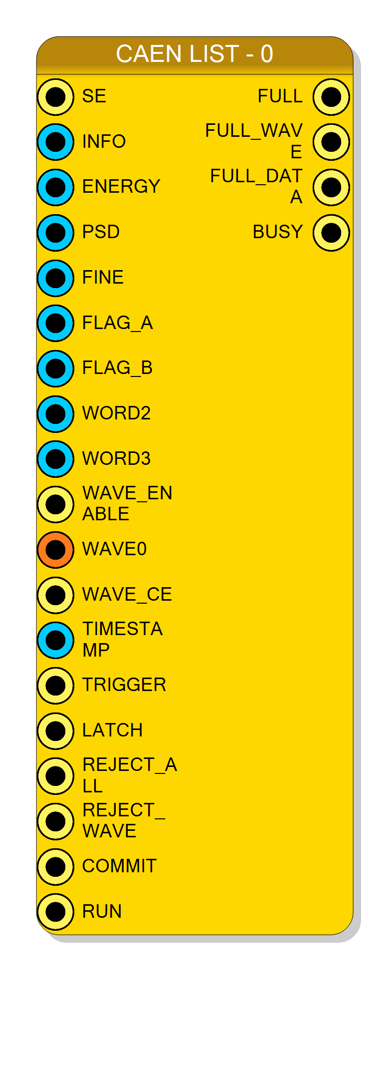
Enable waveform capture for the current event.
- HIGH: Include waveform in event
- LOW: Omit the waveform, keep the parameters
- Unconnected: forced to ‘1’, waveform always included Multi-Words mode only.
Waveform Clock Enable for decimation.
- HIGH: Capture the current 128-bit word
- LOW: Skip the current 128-bit word
- Unconnected: Capture all samples Multi-Words mode only.
Event trigger input. L→H transition starts event capture:
- Latches parameter inputs
- Begins waveform acquisition
- Event not transferred until COMMIT (or AUTO mode)
Global acquisition enable.
- HIGH: Events are accepted
- LOW: Events are ignored
- Unconnected: Always enabled
User-defined data words for custom event format.
- WORD1: 62 bits, User defined word mode only
- WORD2: 63 bits
- WORD3: 63 bits WORD2 and WORD3 are present in both first-word modes.
Properties
Readout channel FIFO
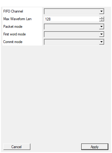
Default: 0
Options: 0 1 2 3 4 5 6 7 8 9 10 11 12 13 14 15
Maximum number of 64 bit waveform samples length
Default: 128
Select between single word packet and multi word packet (only multi-words packed support waveforms)
Default: Multi-Words
Options: Multi-Words Single-Word
Organization of the first word fields of the packet
Default: Predefined fields
Options: Predefined fields User defined word
Select between AUTO (commit after wave), MANUAL (commit signal must be triggered after the end of the wave), DELAYED (Latch commit data and send after wave), PROMPT (commit immediately on commit signal)
Default: AUTO
Options: AUTO MANUAL DELAYED PROMPT
Event packet format.
- Multi-Words: Full event with parameters and waveforms
- Single-Word: Compact format (energy + timestamp only) Default: Multi-Words.
Organization of first parameter word.
- Predefined fields: CAEN-compatible layout (ENERGY, PSD, FLAGS)
- User defined word: Custom 62-bit data Default: Predefined fields. Multi-Words mode only.
Event commit behavior.
- AUTO: Commit after waveform length reached
- MANUAL: Wait for explicit COMMIT signal
- DELAYED: Latch reject flags, commit after wave
- PROMPT: Commit immediately on COMMIT signal Default: AUTO.
Usage
Event Structure
Events consist of parameters (mandatory) and waveforms (optional):
┌────────────────────────────────────────────┐
│ EVENT │
├────────────────────────────────────────────┤
│ Word 1: SE | INFO | ENERGY | PSD | FLAGS │ ← Parameters
│ Word 2: User data (optional) │
│ Word 3: User data (optional) │
├────────────────────────────────────────────┤
│ Waveform samples (0-512) │ ← Optional
└────────────────────────────────────────────┘
Packet Modes
Multi-Words Mode
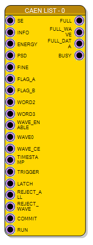
Full event packet with parameters and optional waveforms. Supports:
- Multiple parameter words
- Waveform data up to 512 samples
- Flexible data organization
Single-Word Mode
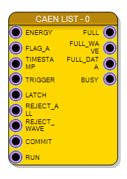
Compact single-word event for high-rate applications:
- Only ENERGY, FLAG_A, and TIMESTAMP
- No waveform support
- Optimized readout throughput
First Word Organization
When using Multi-Words mode, you can choose between:
Predefined Fields (CAEN Compatible)
Standard CAEN FELib-compatible bit layout:
| Field | Size | Description |
|---|---|---|
| SE | 1 bit | Special Event flag |
| INFO | 7 bits | Info field |
| ENERGY | 16 bits | Energy value (PHA/QDC) |
| PSD | 16 bits | Pulse Shape Discriminator |
| FINE | 10 bits | Fine timestamp |
| FLAG_A | 8 bits | User flag A |
| FLAG_B | 12 bits | User flag B |
User Defined Word
Complete control over the first word (62 bits):
- WORD1: 62-bit arbitrary data
- WORD2: 63-bit arbitrary data
- WORD3: 63-bit arbitrary data
Waveform Input
This block has one waveform input, WAVE_0, and it is not configurable: it is a 16-bit time-multiplexed port with TM factor 8, i.e. 128 bits per clock cycle. Whatever drives it must be a TM block of the same factor. There is no property that changes the number or the width of the waveform pads.
WAVE_ENABLE decides per event whether the waveform is appended, and WAVE_CE decides per clock cycle whether the current 128-bit word is taken. Both default to ‘1’ when left unconnected, so a block with neither connected records the waveform of every event at full rate.
Commit Modes
The commit signal controls when events are flushed to the readout FIFO:
| Mode | Description | Use Case |
|---|---|---|
| AUTO | Commit after waveform completes | Simple applications |
| MANUAL | Assert COMMIT after wave ends | Custom timing control |
| DELAYED | Latch reject flags, send after wave | Pile-up rejection |
| PROMPT | Commit immediately on signal | Partial waveforms |
AUTO mode: Simplest - just connect TRIGGER, leave COMMIT unconnected.
MANUAL/DELAYED/PROMPT modes: Provide control over event rejection and timing.
Event Timing Diagram
Sequence:
- TRIGGER L→H starts event capture
- LATCH (optional) captures parameters before trigger
- ENERGY and other parameters latched
- WAVE_0 samples captured sequentially, 8 per clock
- COMMIT L→H flushes event to FIFO
- BUSY goes low when ready for next event
Reject Signals
Control event acceptance between TRIGGER and COMMIT:
| Signal | Effect |
|---|---|
| REJECT_ALL | Discard entire event (parameters + waveform) |
| REJECT_WAVE | Keep parameters, discard waveform only |
Use cases:
- Pile-up rejection
- Pulse shape discrimination filtering
- Coincidence/anti-coincidence logic
Status Outputs
| Output | Description |
|---|---|
| FULL | Channel FIFO full - new events will be rejected |
| FULL_WAVE | Waveform buffer full - waveforms will be truncated |
| FULL_DATA | Parameter buffer full - events will be rejected |
| BUSY | New triggers not accepted (processing current event) |
Best practice: Monitor FULL signals and gate triggers when buffers are full.
Channel Assignment
The FIFO Channel property (0-15) selects the readout endpoint, one per board channel. Each channel is independent:
- One List block per channel
- Channels have independent FIFOs
- Software reads each channel endpoint separately
Note: The channel number does NOT automatically correspond to physical input channel. You must manually connect the correct analog input to each List block.
Typical DPP Processing Chain
┌─────────────┐ ┌──────────────┐ ┌──────────────┐
│ X2751 │ │ Digital │ │ X2751 │
│ Digitizer │────►│ Processing │────►│ List │
│ (ADC) │ │ Chain │ │ (DPP) │
└─────────────┘ └──────────────┘ └──────────────┘
│
▼
┌──────────────┐
│ - Trigger │
│ - Energy │
│ - PSD │
│ - Timestamp │
└──────────────┘
Resources & Timing
-
Latency: 1-2 clock cycles for trigger/commit detection
-
Throughput: Up to 1 event per clock cycle (depends on waveform length)
- Maximum 512 waveform words per event
- 16 selectable channel endpoints, each with its own FIFO
- Waveform input is time-multiplexed with TM factor 8 (128 bits per clock, 1 GS/s)
- Data transferred via CAEN FELib or SciCompiler SDK
Supported Boards
- X2751