ISIS PSD TM
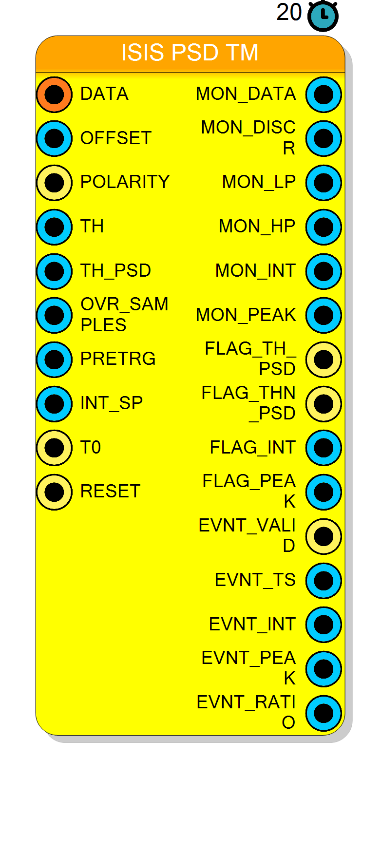
Time-multiplexed pulse-shape-discrimination front-end for the NI DAQ121. It takes four ADC samples per clock, discriminates them against a threshold, shapes the discriminator output with a fixed low-pass + high-pass IIR pair and starts a charge integration when the shaped signal stays over the PSD threshold long enough. Up to four events are integrated concurrently; each one produces a timestamp, a charge integral, a peak amplitude and (optionally) the integral/peak ratio.
Introduction
Principle of Operation
ISIS PSD TM is a Vitis HLS core (isispsd.cpp) generated and synthesised by the compiler
for every distinct parameter set. It is a time-multiplexed block: the DATA pin carries
TM = 4 samples of 16 bit in one 64-bit word per clock, so on the NI DAQ121
(acquisition clock CLK_ACQ = 250 MHz) the block processes 1 Gsample/s.
The block splits the stream in two paths:
- a trigger path that works on the average of the four samples of the clock, turns it into a rectangular discriminator pulse and shapes that pulse with two cascaded IIR filters. The width of the shaped pulse is what discriminates one particle species from another (the classic pulse shape discrimination);
- an integration path that works on the raw four lanes after a programmable delay, so that the charge integration can start before the sample that fired the trigger.
DATA[63:0] = lane3 | lane2 | lane1 | lane0 (lane0 = bits 15..0 = oldest sample)
|
|--> per lane: x_i = lane_i - OFFSET , negated when POLARITY = 1
| |
| +--> data16 = (x0+x1+x2+x3) >> 2 ---> compare with TH ---> MON_DISCR
| |
| low-pass IIR --+--> MON_LP
| |
| high-pass IIR -+--> MON_HP --> compare TH_PSD
| |
| OVR_SAMPLES consecutive clocks --+
| |
+--> 128-word delay line (PRETRG clocks) --> d0..d3 ---------------> integrate
The energy of an event is the sum of the four delayed lanes accumulated over INT_SP clocks:
$$ \mathrm{EVNT_INT} ;=; \sum_{n=0}^{\mathrm{INT_SP}-1};\sum_{i=0}^{3} d_i[n] $$
and the peak is the largest single sample seen inside that window:
$$ \mathrm{EVNT_PEAK} ;=; \max_{n,i}; d_i[n] $$
Because INT_SP and PRETRG are counted in clock cycles, every unit is worth
TM = 4 samples (4 ns at 250 MHz).
Pin Description
x"0000".
x = -(lane - OFFSET)), which turns negative-going pulses into positive ones.
Default when left open: '0'.
ap_stable). Default when left open: x"01FF" (511).
MON_HP.
Crossing it raises FLAG_TH_PSD and starts the over-threshold counter.
Treated as constant (ap_stable). Default when left open: x"000F" (15).
TH_PSD before an
event is armed; the comparison is strict (count > OVR_SAMPLES), and a single clock
below TH_PSD resets the count. One unit = 4 input samples.
Treated as constant (ap_stable). Default when left open: x"000A" (10).
ap_stable). Default when left open: x"000A" (10).
4 × INT_SP samples.
Treated as constant (ap_stable). Default when left open: x"00A0" (160).
'0'.
ap_rst of the HLS IP). Left open it is tied to the project global reset.
TH, otherwise 0.
TH_PSD.
MON_HP is above TH_PSD (level).
OVR_SAMPLES and a new event is armed.
EVNT_* pins.
At most one event per clock is emitted; slots are drained in the order 0, 1, 2, 3.
EVNT_TS = timestamp + 4 × PRETRG. The internal counter is cleared by T0.
INT_SP clocks.
Internal mode: (EVNT_INT << 8) / EVNT_PEAK — the integral/peak ratio in Q8.
External mode: the constant 1 (do the division outside the block).
Properties
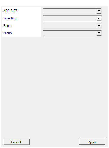
Set the number of raal bits of the board ADC
Nominal number of ADC bits. It does not change the generated core — the value only enters the MD5 that names the HLS IP, so changing it re-synthesises an identical core. Values: 12, 13, 14. Default: 12.Default: 12
Options: 12 13 14
Set number of samples for each clock cycle
Number of samples carried per clock onDATA. The core is hard-wired to four lanes
(64-bit data port, timestamp step of 4, four-term accumulator) and the combo therefore
offers a single value. Changing it rebuilds the symbol.
Default: 4.
Default: 4
Options: 4
Set if make division internal or external
Where the integral/peak division is performed.
| Value | Effect |
|---|---|
External |
EVNT_RATIO is the constant 1; declared block latency 20 clocks |
Internal |
EVNT_RATIO = (EVNT_INT << 8) / EVNT_PEAK; declared block latency 55 clocks |
The value is part of the HLS IP name, so both variants can coexist in one project. Changing it rebuilds the symbol. Default: External.
Default: External
Options: External Internal
Set if stop integral on pileup or use a secondary integrator to process events
What happens to an integration that is still running when a new event is armed.
| Value | Effect |
|---|---|
Stop Integral |
the older integration is terminated at once and committed early |
Continue |
the older integration runs to the full INT_SP |
The property is not part of the HLS IP name, so two blocks that differ only here
share one IP. Its shipped default (External) is not a valid combo value, and with it
the core behaves as Continue.
Default: External (behaves as Continue).
Default: External
Options: Stop Integral Continue
⚙️ Detailed Operation
Lane unpacking and the TM factor
The symbol pin DATA is declared TYPE_STD_LOGIC_VECTOR_TM, 16 bit wide, with
TimeMultiplexed = 4; the HDL pad that is actually generated is a plain 64-bit port
named data. Following the repo-wide TM convention, lane 0 lives in the low bits and is
the oldest sample of the clock. The core unpacks it as
datax_0 = (data >> 0) & 0xFFFF; // oldest
datax_1 = (data >> 16) & 0xFFFF;
datax_2 = (data >> 32) & 0xFFFF;
datax_3 = (data >> 48) & 0xFFFF; // newest
Each lane has OFFSET subtracted and is negated when POLARITY = 1
(x = -(lane - OFFSET)), so OFFSET is the pedestal of the digitiser and POLARITY
makes negative-going pulses positive.
The Time Mux property only offers the value 4 — the core is hard-wired to four lanes
(data is 64 bit, the timestamp advances by 4 per clock, the integrator adds four terms).
Trigger path
-
Lane average.
data16 = (x0 + x1 + x2 + x3) >> 2— the mean of the four samples of the clock. This is the only signal compared againstTH; the block therefore triggers on a 250 MHz decimated version of the 1 GS/s stream. -
Discriminator.
MON_DISCRis a rectangular pulse:data16 > TH ? 6553 : 0, where6553 = (int)(0.2 × 0x7FFF). Its width carries the pulse-shape information. -
Low-pass section — a 2nd-order IIR written in scattered look-ahead form, which is what lets Vitis close II = 1 at 4 ns:
$$ y[n] ;=; \sum_{k=0}^{6} b_k,x[n-k] ;-; a_1,y[n-3] ;-; a_2,y[n-6] $$
with the coefficients compiled into
isispsd.cpp:coefficient value $a_1$ -1.691126416184245 $a_2$ 0.7213785295739619 $b_0 \dots b_6$ 0.00093575, 0.00364298, 0.00699309, 0.00838898, 0.00644455, 0.00309409, 0.00075267 The result is exported on
MON_LP. -
High-pass section — same idea, 4 feed-forward taps and one feedback tap at $n-3$:
$$ y[n] ;=; \sum_{k=0}^{3} b_k,x[n-k] ;-; a_1,y[n-3] $$
coefficient value $a_1$ -0.8599680957679054 $b_0 \dots b_3$ 0.97547839, -0.0478406, -0.04549434, -0.88214345 The result is exported on
MON_HP.Coefficients are stored as
ap_fixed<18,2>(2 integer bits, 16 fractional bits) and the filter states asap_fixed<24,16>. -
PSD decision. While
MON_HP > TH_PSD,FLAG_TH_PSDis high and an internal counter runs. When that counter becomes strictly greater thanOVR_SAMPLES(and the previous crossing has been released),FLAG_THN_PSDpulses for one clock and an integrator slot is armed. Dropping belowTH_PSDfor a single clock resets the counter to zero, so theOVR_SAMPLESclocks must be consecutive.
Integration path and the pre-trigger delay line
The raw 64-bit word is pushed into a 128-entry circular delay line (one entry = one clock
= 4 samples) and read back PRETRG clocks later:
delay1[write_pointer1] = data;
read_pointer1 = write_pointer1 - (int)offset_samples; // offset_samples = PRETRG
if (read_pointer1 < 0) read_pointer1 += 128;
Four parallel integrators (PARALLEL_INTEGRATOR = 4) are available. When an event is
armed, the first slot that is neither integrating nor waiting to be committed is taken; its
accumulator, sample counter and peak register are cleared and its start timestamp is latched.
While a slot is running it adds the four delayed lanes every clock and keeps the maximum of
the four lanes:
p_integral[i] += datad_0 + datad_1 + datad_2 + datad_3; // one clock = 4 samples
if (datad_max > p_maxv[i]) p_maxv[i] = datad_max;
After INT_SP clocks the slot stops and is marked to be committed.
Pile-up handling (Pileup property)
The allocation loop walks the slots from 0 upwards; every busy slot it passes before finding
a free one has its peak-running flag cleared. What that means depends on the property, which
is injected as a #define at the top of the generated .cpp:
Pileup |
#define emitted |
Behaviour of the older, still-running events |
|---|---|---|
Stop Integral |
STOP_INTEGRAL_ON_PILEUP 1 |
integration stops immediately and the event is committed with a short window |
Continue |
(none) | integration runs to the full INT_SP regardless of the new trigger |
FLAG_PEAK exports the per-slot peak-running bitmap, so FLAG_INT and FLAG_PEAK differ
exactly on the slots that have been hit by a pile-up.
Event output
Committed slots are drained with a fixed priority (slot 0 first, then 1, 2, 3), at most one
event per clock. On that clock EVNT_VALID is high for one cycle and EVNT_TS, EVNT_INT,
EVNT_PEAK and EVNT_RATIO are valid.
The internal timestamp counts samples: it is incremented by 4 on every clock and cleared
to 0 while T0 is high. The value latched when the event is armed is
$$ \mathrm{EVNT_TS} ;=; t_{\text{sample}} ;+; 4\cdot\mathrm{PRETRG} $$
(the core computes timestamp - ((0 - offset_samples) << 2), i.e. it adds four times the
pre-trigger; the sign is as written in the source).
EVNT_RATIO depends on the Ratio property:
Ratio |
#define emitted |
EVNT_RATIO |
|---|---|---|
External |
(none) | constant 1 — do the division outside the block |
Internal |
INTERNAL_RATIO 1 |
(EVNT_INT << 8) / EVNT_PEAK, i.e. the ratio in Q8 |
Monitor outputs
| Pin | Content |
|---|---|
MON_DATA |
lane 0 of the delayed, offset- and polarity-corrected data |
MON_DISCR |
discriminator output (0 or 6553) |
MON_LP |
low-pass filter output |
MON_HP |
high-pass filter output |
MON_INT |
running integral of slot 0 only |
MON_PEAK |
running peak of slot 0 only |
FLAG_INT |
bits 3:0 = slot busy (16-bit port, upper bits 0) |
FLAG_PEAK |
bits 3:0 = slot peak-running |
MON_INT / MON_PEAK are not an event stream — they follow slot 0 and are meaningless
while slot 0 is idle.
Generated hardware, clock and build
CompileHDLwritesHLS/<unique>/isispsd.cpp(with the#defines prepended) and ahls_compile.tclthat runscsynth_designwithset_directive_top -name <unique> isispsd, targeting the project FPGA part and a clock period offloor(1000000 / AcquisitionClockFreq)ns — 4 ns on the NI DAQ121, whoseCLK_ACQis 250 MHz. All generated VHDL is merged intoHDL/pcores/<unique>.vhd.- The IP name is
isispsd_<8 letters>where the letters are an MD5 of (component name, ADC BITS, Time Mux, Ratio). - The core is free-running:
#pragma HLS PIPELINE II=1and#pragma HLS INTERFACE ap_ctrl_none port=return, so there is no start/done handshake.ap_clkis tied to the project acquisition clock automatically — there is no CLK pin on the symbol — andap_rstto the project global reset whenRESETis left open.
There is no CompileMMC / CompileSDK content: the block exposes no software registers.
Everything is configured through pins, so use constant blocks or a register block to drive
TH, TH_PSD, OVR_SAMPLES, PRETRG and INT_SP.
Resources & Timing
-
Latency: Declared block latency: 20 clocks with Ratio = External, 55 clocks with Ratio = Internal
-
Throughput: One 64-bit word (4 samples) per clock, II = 1; at most one event per clock on EVNT_VALID
- 4 concurrent integrators (
PARALLEL_INTEGRATOR = 4); a 5th simultaneous event is dropped. - 128-entry × 64-bit pre-trigger delay line.
- Filter coefficients are
ap_fixed<18,2>, filter statesap_fixed<24,16>. - Synthesised for a clock period of
floor(1000000 / AcquisitionClockFreq)ns (4 ns on the NI DAQ121, 250 MHz); LUT/DSP/BRAM figures are whatever Vitis reports for that run and are not fixed by the source.