
RF Sequential FIR (fixed coefs)
Time-shared (sequential) FIR filter with coefficients baked into the netlist. A single MAC unit is re-used over all NumTaps taps within the SysClk / DataClk window, so a long filter (high order) costs only one multiplier per channel instead of one multiplier per tap. Ideal for decimated / low-rate baseband where the sample period spans many system clocks. Real or complex I/Q. Designed and quantised in the built-in FIR Designer.
Introduction
The Sequential FIR (fixed coefs) block computes a standard FIR
y[n] = sum_{k=0..NumTaps-1} h[k] * x[n-k]
but instead of laying down NumTaps parallel multipliers it uses one
time-shared MAC that walks the taps one per system-clock cycle. This
is the natural architecture when the data rate is far below the system
clock: the block accepts one input sample every ClockRatio system
clocks (a “gapped” stream), and it has that whole window to sweep the
MAC across every tap.
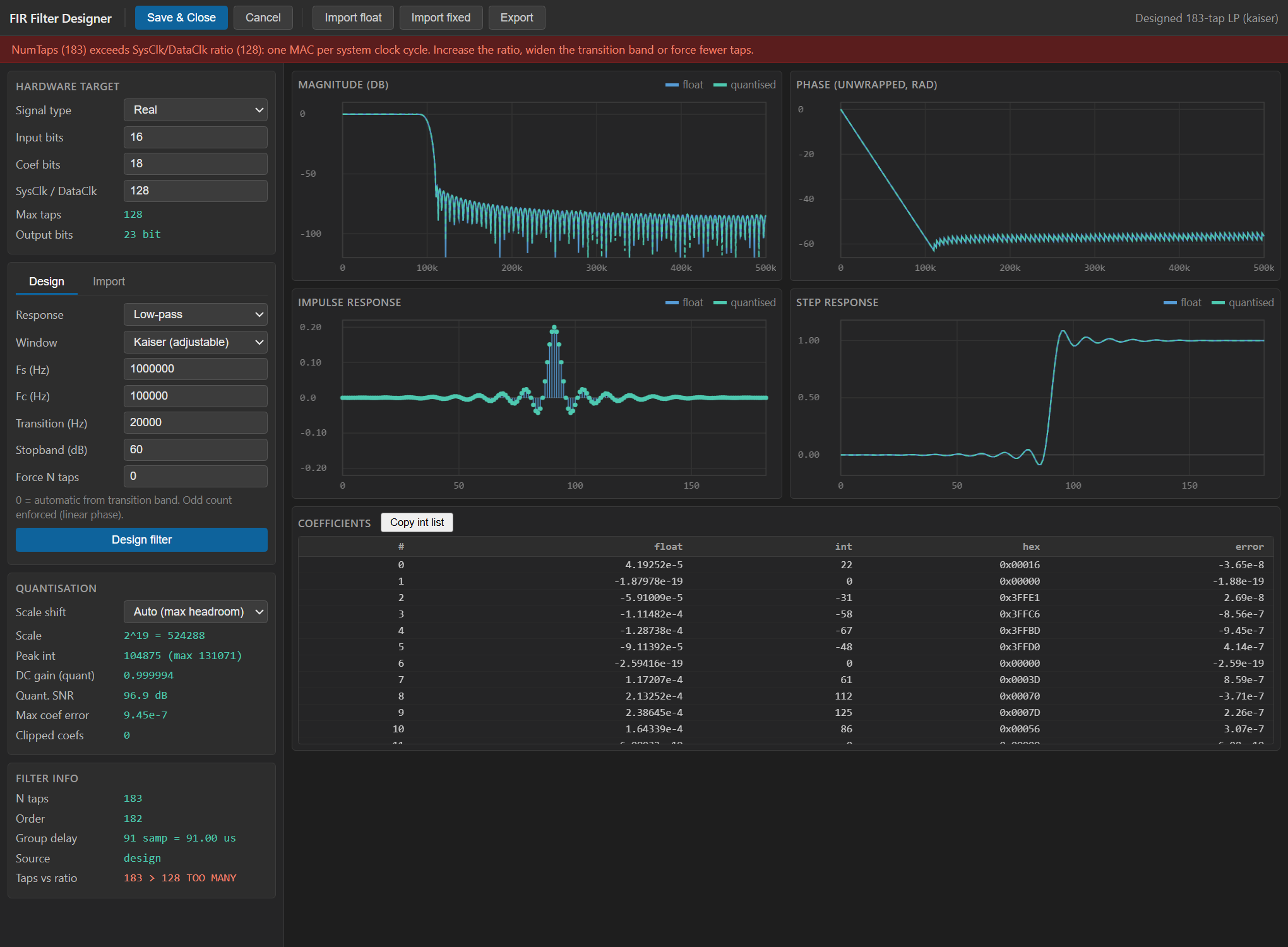
The block uses a custom WebView2 graphical designer (the FIR
Designer, shown above) instead of the standard property grid.
Double-clicking the block opens the designer, where you specify the
response (low-pass / high-pass / band-pass / band-stop, window or
equiripple method, cut-off / transition / attenuation), see the live
magnitude response and pole/zero-free tap stem plot, pick the hardware
widths and the SysClk / DataClk ratio, and read off the resource /
timing estimate. On Save & Close the designer writes the quantised
integer coefficients and the hardware parameters back into the block;
they are baked into the generated HLS at synthesis time and are not
exposed to the fabric.
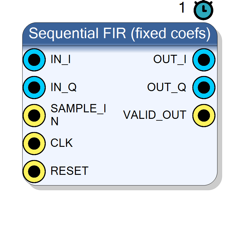
SAMPLE_IN ┐ (1 pulse per new input sample, gapped every ClockRatio)
IN_I / IN ┤ [ 1x time-shared MAC over NumTaps ] ── OUT_I / OUT
IN_Q ┘ └─ OUT_Q
VALID_OUT ── (pulse when result ready)
(h[k] baked in by the FIR Designer)
For a run-time reloadable version see Component_SeqFIRProgrammable
(seq_fir_prog). For a fully-parallel (one-multiplier-per-tap, II=1 at
the full clock) filter see Component_FIR (fir).
Pin Description
SysClk cycle each time a new
input sample is valid on IN / IN_I / IN_Q. The block then has
ClockRatio cycles to sweep the MAC over all taps. Must fire no more
often than once every NumTaps cycles.
SysClk). Default: Acquisition clock.
SysClk cycle when a new
filtered result is presented on the output pins, i.e. once the MAC
sweep over all NumTaps taps has completed.
Properties
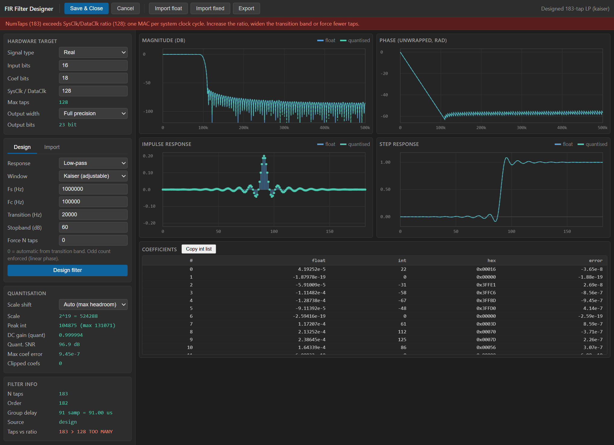
Real: one channel. Complex: independent I/Q with the same real coefficients.
Real (single channel, pinsIN / OUT, one multiplier) or
Complex (independent I/Q on IN_I/IN_Q and OUT_I/OUT_Q
sharing one real coefficient set, two multipliers). Default
Complex. Set in the FIR Designer.
Default: Complex
Options: Real Complex
Bit width of the input sample(s) (signed).
Bit width of each signed input sample. Range 4 to 32, default 16.Default: 16
Options: 4 5 6 7 8 9 10 11 12 13 14 15 16 17 18 19 20 21 22 23 24 25 26 27 28 29 30 31 32
Bit width of each coefficient (signed).
Bit width of each signed coefficient. One of 10, 12, 14, 16, 18, 20, 24. Larger = lower stop-band error floor at the cost of DSP width. Default 18.Default: 18
Options: 10 12 14 16 18 20 24
Filter order + 1. Must be <= ClockRatio.
Number of filter taps (filter order =NumTaps - 1). One of
8, 16, 24, 32, 48, 64, 96, 128, 192, 256, 384, 512, 768, 1024.
Must be <= ClockRatio (one tap is MAC’d per system clock).
Default 64. The FIR Designer may override this with its own
generated tap count (a warning is emitted if they differ).
Default: 64
Options: 8 16 24 32 48 64 96 128 192 256 384 512 768 1024
System-clock cycles per input sample. Must be >= NumTaps (one MAC per SysClk cycle).
SysClk / DataClk: the number of system-clock cycles between input
samples (the width of the MAC-sweep window). One of
8, 16, 32, 64, 128, 256, 512, 1024, 2048, 4096. Must be >=
NumTaps. Default 128.
Default: 128
Options: 8 16 32 64 128 256 512 1024 2048 4096
The filter’s spec + quantised coefficients, produced by the FIR Designer.
Hidden text property holding the FIR Designer output as JSON: the filter spec, the quantised integer coefficients (h_int), the tap
count (n_taps) and the accumulator shift (shift). Never shown in a
grid — the whole block is edited through the FIR Designer. If empty,
compilation fails asking you to open the designer and press
Save & Close.
Full = full-precision accumulator. InputSat = input width, »shift then saturate. InputShift = input width, MSBs kept.
Default: Full
Options: Full InputSat InputShift
Usage
Time-sharing / clock-ratio concept
A conventional direct-form FIR needs NumTaps DSP multipliers because it
finishes a full convolution every clock. When the data is slow relative
to the fabric clock, that is wasteful: the multipliers sit idle most of
the time. The sequential FIR instead uses the idle cycles.
CLKruns at the system clock (SysClk, typically the acquisition clock).- A new input sample is presented only once every
ClockRatiosystem clocks.SAMPLE_INis pulsed high for oneSysClkcycle to mark it; the sample rate isDataClk = SysClk / ClockRatio. - On the
SAMPLE_INpulse the block shifts the new sample into the delay line, clears the accumulator and starts a counter. - On each following
SysClkcycle it performs exactly one MAC:acc += delay[cnt] * h[cnt], incrementingcnt. - After
NumTapscycles the accumulation is complete: the block right- shifts the accumulator, drives the result onOUTand pulsesVALID_OUTfor one cycle.
Because one tap is processed per system clock, the whole sweep must fit inside the inter-sample window:
NumTaps <= ClockRatio (checked at compile time)
If NumTaps > ClockRatio the compile fails with an error asking you to
raise ClockRatio or lower NumTaps. The MAC therefore needs only
one multiplier (real) or two (complex I/Q), independent of the
filter length — the cost is throughput, not area.
Bit widths and scaling
Data is signed two’s complement. Internally:
ACC_SIZE = InputSize + CoefSize + 8 (8 guard bits)
OUT_SIZE = ACC_SIZE - CoefShift
= InputSize + CoefSize + 8 - CoefShift
The 8 guard bits let the accumulator sum up to 256 taps without
overflow. CoefShift is the right-shift applied to the accumulator to
restore unity DC gain; the FIR Designer stores the exact shift it used
when quantising (shift in the project JSON). When absent it defaults to
CoefSize - 1, in which case OUT_SIZE = InputSize + 9.
Complex vs real
- Real: one channel — pins
IN/OUT, one multiplier. - Complex: independent I and Q sharing the same real coefficient
set — pins
IN_I/IN_QandOUT_I/OUT_Q, two multipliers. This is the usual case after a complex mixer.
Coefficient generation (FIR Designer)
The designer quantises the floating-point prototype h_float[k] to a
signed CoefSize-bit integer array h_int[k] with a scale of
2^(CoefSize-1) - 1, records the tap count (n_taps) and the accumulator
shift (shift), and stores everything as JSON in the hidden FIRProject
property. The HLS side reads h_int directly into a compile-time ROM, so
Vivado can prune zero / trivial coefficients.
Visual designer
This block has no plain property grid. Every parameter — signal type,
input / coefficient widths, tap count, SysClk / DataClk ratio and the
filter response itself — is edited inside the FIR Designer that opens on
double-click (see the screenshot in the introduction). The designer
offers a MATLAB-like workflow: choose the filter template, tune the
frequency spec, watch the magnitude response and tap plot update live,
and check the estimated multiplier count and MAC latency before pressing
Save & Close. The hidden FIRProject property carries the resulting
spec + coefficients; the visible hardware properties documented below are
mirrored from the designer so that symbol drawing and HDL generation keep
working off ordinary property values.
Latency and throughput
#pragma HLS PIPELINE II=1: the core advances one MAC per system clock.- End-to-end latency from
SAMPLE_INtoVALID_OUTis aboutNumTapssystem clocks (one per tap). - Sustained throughput is one filtered sample every
ClockRatiosystem clocks, i.e. the inputDataClkrate. - All ports use the
ap_noneinterface (no ready/valid handshake beyondSAMPLE_IN/VALID_OUT).
Reset
RESET is the HLS synchronous reset (ap_rst): it clears the delay
line, the accumulator and the tap counter.
Typical applications
- Long channel-select filter on an already-decimated stream where a parallel FIR would burn hundreds of DSPs.
- Sharp baseband LPF after a CIC / halfband decimator.
- Pulse-shaping / matched filter at a low symbol rate.
Resources & Timing
-
Latency: ~NumTaps system-clock cycles from SAMPLE_IN to VALID_OUT
-
Throughput: One sample every ClockRatio system clocks (the DataClk rate)
Implemented with Vitis HLS. Only one DSP multiplier for Real, two
for Complex I/Q, regardless of filter length — the MAC is time-shared
across taps (one MAC per system clock, II=1). Compile-time constant
coefficients let Vivado prune zero / trivial taps. A delay line of
NumTaps samples (per channel) is kept in registers / SRL. Hard
constraint enforced at compile: NumTaps <= ClockRatio.