
RF Goertzel Multi (tone bank)
Multi-frequency Goertzel tone monitor. Watches several user-chosen DFT bins with a SINGLE time-shared multiplier (one bin updated per system clock) instead of one resonator per frequency. Emits one POWER output per monitored tone. Typical use: DTMF / multi-tone decoding, monitoring a handful of pilots or spectral lines with minimal DSP.
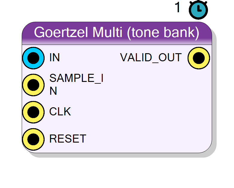
Introduction
The Goertzel Multi (tone bank) block monitors several frequencies at
once, each as an independent DFT bin, but reuses one time-shared
multiplier across all of them rather than instantiating a separate
resonator per tone. It emits one POWER_b output pin per monitored
frequency plus a shared VALID_OUT.
Each bin runs the same second-order Goertzel resonator as the single-tone block:
s[n] = x[n] + 2*cos(w_b)*s[n-1] - s[n-2] (w_b = 2*pi*k_b/N)
but the per-sample recurrence is iterated one bin per system clock:
between two input samples the core steps through all NUM_FREQS bins in
turn. Because of this the block needs at least NUM_FREQS system clocks
per input sample, controlled by the SysClk / DataClk ratio
(ClockRatio >= number of frequencies). Resource cost is a small fixed
number of multipliers regardless of how many tones are monitored, versus
one (real) or two (complex) multipliers per tone for a parallel bank.
Every frequency is snapped to its nearest DFT bin k_b = round(N*f_b/Fs);
all bins share the same block length N, so they share the same
resolution Fs/N and update together every N samples.
For a single tone use Component_Goertzel; for a per-sample sliding output use Component_GoertzelSliding.
Pin Description
NUM_FREQS system clocks between pulses
(ClockRatio >= number of tones) so the time-shared core can step
every bin.
ClockRatio
times faster than the data rate.
POWER_0, POWER_1, …), in the
order the frequencies were added in the designer. Carries that bin’s
power |X(k_b)|^2, updated every N samples and held between updates.
Each is 2(InputSize + ceil(log2 N) + 2) + 4* bits.
Properties
Real: one input channel. Complex: I/Q input.
Real: single input channelIN. Complex: I/Q input
IN_I / IN_Q (true one-sided bins; two recurrences per tone).
Default Real.
Default: Real
Options: Real Complex
Bit width of the input sample(s).
Bit width of each signed input sample. Range 4..32, default 16.Default: 16
Options: 4 5 6 7 8 9 10 11 12 13 14 15 16 17 18 19 20 21 22 23 24 25 26 27 28 29 30 31 32
Bit width of the cos/sin coefficients.
Bit width of the signedcos/sin coefficients (scale
2^(CoefSize-2)). One of 12, 14, 16, 18, 20, 24. Default 18.
Default: 18
Options: 12 14 16 18 20 24
DFT size: resolution Fs/N, latency N samples.
Block length = DFT size N, shared by all tones. ResolutionFs/N,
measurement latency N samples. One of
16, 32, 64, 128, 256, 512, 1024, 2048, 4096, 8192. Default 256.
Default: 256
Options: 16 32 64 128 256 512 1024 2048 4096 8192
Sample rate of the data feeding this block.
Sample rate (Hz) of the data feeding this block. Used to map each target frequency to its DFT bink = round(N*f/Fs). Default
1000000.
Default: 1000000
System clocks per input sample. Must be >= number of frequencies.
System clocks per input sample (SysClk / DataClk). Must be >= the number of monitored frequencies, because the time-shared core steps one bin per system clock. One of 2, 4, 8, 16, 32, 64, 128, 256, 512, 1024. Default 16.Default: 16
Options: 2 4 8 16 32 64 128 256 512 1024
The monitored frequencies + coefficients, produced by the Goertzel Designer.
Hidden JSON blob produced by the Goertzel Designer holding the monitored-frequency list, coefficients and hardware config. Managed by the visual designer, not edited by hand. If empty (no tones added) the block fails to compile.Usage
Time-shared resonator bank
The Goertzel algorithm computes a DFT bin as a second-order IIR resonator
(see the single-tone block). This variant keeps a small state array
s1[b], s2[b] (plus s1q/s2q in complex mode) for every monitored bin
b and, instead of updating them all in parallel, walks the array one
entry per system clock:
- On each
SAMPLE_INpulse the new input sample is latched and the bin index is reset to 0. - On each following system clock one bin
bis advanced with its own coefficient2*cos(w_b)(andsin(w_b)for complex). - After all
NUM_FREQSbins have been stepped the core waits for the next sample.
So one input sample is fully processed in NUM_FREQS system clocks; the
rest of the ClockRatio window is idle. This is why the design constraint
is ClockRatio >= NUM_FREQS (enforced at compile time — otherwise the
plugin raises an error telling you to raise SysClk/DataClk or drop tones).
Per-bin math
Identical to the single-tone Goertzel, per bin. Real (SignalType = Real): one recurrence, power from the last two states
power_b = s1_b^2 + s2_b^2 - 2*cos(w_b)*s1_b*s2_b
Complex (SignalType = Complex): two recurrences per bin sharing the
bin’s cos/sin, giving the one-sided complex bin
Xr = s1i - cos(w_b)*s2i - sin(w_b)*s2q
Xi = s1q - cos(w_b)*s2q + sin(w_b)*s2i
power_b = Xr^2 + Xi^2
DFT-bin snapping and resolution
Each requested frequency is mapped to an integer bin:
k_b = round(N * f_b / Fs)
df = Fs / N (shared resolution / bin spacing)
All tones use the same N, so they share the same selectivity (a
~Fs/N-wide main lobe per bin) and complete together. Choose distinct
bins spaced by at least one Fs/N step for clean separation.
Coefficients
For each bin the plugin quantises cos(w_b) and sin(w_b) to signed
CoefSize bits (scale 2^(CoefSize-2)) and writes them into the
generated goertzel_cos.inc / goertzel_sin.inc coefficient ROMs; the
recurrence uses 2*cos(w_b).
Generated top and pins
The HLS worker goertzel_multi_core() is fixed; the plugin generates the
top goertzel_multi() with one explicit power_b output port per
frequency so the diagram symbol grows one POWER_b pin per monitored
tone. Adding or removing tones in the designer changes the pin count and
triggers a redesign.
Bit widths
Data is signed two’s complement.
IN/IN_I/IN_Q: signedInputSizebits.- Each
POWER_b:POW_SIZE = 2*STATE_SIZE + 4bits, whereSTATE_SIZE = InputSize + ceil(log2 N) + 2.
Timing and handshake
#pragma HLS PIPELINE II=1,ap_ctrl_none: free-running.SAMPLE_INpulses once per input sample; there must be at leastNUM_FREQSsystem clocks between pulses (ClockRatio >= NUM_FREQS).VALID_OUTpulses one clock when a fresh block completes; at that point everyPOWER_bis simultaneously updated. Between updates eachPOWER_bholds its last value.- Measurement latency is
Nsamples (all tones update together).
Reset
RESET (ap_rst) clears every bin’s states and the sample counter; the
states are also cleared at the end of each block.
Visual designer
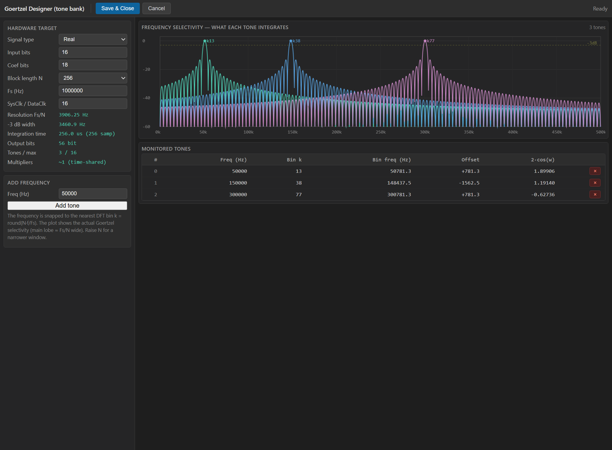
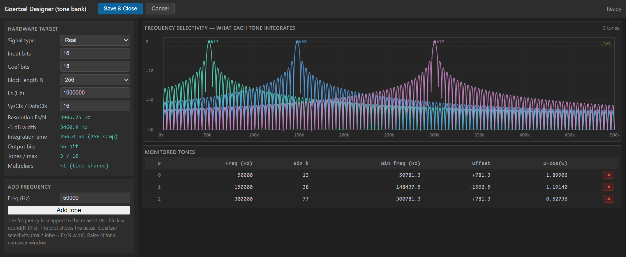
This block is configured through the Goertzel Designer (a WebView2
graphical tool), not the property grid. Double-click the block to open
it. In multi mode you set the hardware target (signal type, input/
coefficient bits, block length N, Fs and the SysClk / DataClk ratio),
then add each frequency to monitor with the “Add tone” control. The
tool snaps every tone to its nearest DFT bin k = round(N*f/Fs), overlays
all tones on the frequency-selectivity plot (each bin’s Goertzel main
lobe, ~Fs/N wide, showing what it integrates) and shows a live
resource / result estimate: resolution Fs/N, -3 dB width,
integration time, output bits, tones-vs-max (the ClockRatio budget) and
multiplier count. Save & Close writes the tone list and quantised
coefficients into the block, creating one POWER_b pin per tone.
Typical applications
- DTMF / multi-tone signalling decode (all keypad tones at once).
- Multi-pilot monitoring in a modulated carrier.
- Sparse spectral analysis: a handful of lines instead of a full FFT.
- Cheap tone bank where DSPs are scarce and the data rate leaves spare system-clock cycles.
Resources & Timing
-
Latency: 1 clock per bin step; a new POWER set every N samples (block latency = N samples)
-
Throughput: 1 input sample every ClockRatio system clocks; ClockRatio >= number of tones
Implemented with Vitis HLS. A single time-shared multiplier services all tones (a small fixed multiplier count independent of the number of frequencies), trading latency (NUM_FREQS system clocks per sample) for area versus a parallel resonator bank. Coefficient ROMs (goertzel_cos.inc / goertzel_sin.inc) hold one quantised cos (and sin, complex) per bin. Best when DSPs are scarce and the data rate leaves spare system-clock cycles; if you need one tone per clock with no ratio constraint, instantiate several single-tone Goertzel blocks instead.