Getting Started with DT5550W Citiroc (SiPM Rate Meter)
Tutorial for DT5550W with Citiroc ASIC readout. Learn to configure the Weeroc Citiroc ASIC, control high voltage for SiPM bias, implement multi-channel rate meter, and test with Resource Explorer. Complete guide for SiPM-based photon counting and rate measurement applications.
Introduction
This tutorial demonstrates how to configure the DT5550W board with Citiroc ASIC piggyback for Silicon Photomultiplier (SiPM) readout and photon counting with rate measurement.
About DT5550W with Citiroc
The DT5550W is a complete readout system based on Weeroc ASICs. The Citiroc (Cherenkov Imaging Time Imaging ReadOut Chip) is specifically designed for SiPM array readout and provides:
- 32 channels per ASIC (up to 128 channels with 4 ASICs)
- Charge measurement and time measurement on each channel
- Individual trigger outputs per channel
- Integrated discriminators with adjustable thresholds
- On-board HV generation for SiPM bias (20-85V)
- Low noise charge-sensitive preamplifiers
- Variable shaping time for optimization
What You’ll Learn
- Configuring Citiroc ASIC parameters
- Controlling on-board high voltage for SiPM bias
- Implementing multi-channel rate meters in FPGA
- Testing photon counting with Resource Explorer
- Using Weeroc configuration tools in SCI-Compiler
- Measuring trigger rates on all channels
Hardware Requirements
For this tutorial you need:
- DT5550W Citiroc board (with Citiroc piggyback)
- SiPM matrix (e.g., Hamamatsu S13361-3050AE-08)
- Dark box (provided with DT5550W kit)
- Light pulser (e.g., CAEN SP5601 or equivalent)
- Optical fiber
- USB 3.0 cable for communication
- JTAG cable for FPGA programming
Hardware Setup
Experimental Setup
The photon counting experiment setup consists of:
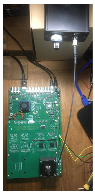
Figure 1: DT5550W Citiroc experimental setup with SiPM, dark box, and light pulser
Setup description:
- SiPM matrix is installed on the Citiroc piggyback board
- Dark box shields the SiPM from ambient light
- Light pulser generates optical pulses via fiber
- Optical fiber delivers light to the SiPM
- DT5550W processes signals and measures trigger rates
Signal Flow
Light Pulser → Optical Fiber → SiPM → Citiroc ASIC → FPGA Rate Meters
When light hits the SiPM:
- SiPM generates electrical pulse
- Citiroc ASIC discriminates signal above threshold
- Trigger output transitions from 0→1
- FPGA rate meter increments counter
- Rate value updated every second
Firmware Design Overview
Project Goals
The firmware implements three main functions:
- Configure the Citiroc ASIC (thresholds, polarity, mode)
- Control high voltage generator (SiPM bias)
- Measure trigger rates on all channels (multi-channel rate meter)
Block Diagram
SCI-Compiler provides dedicated blocks for Weeroc ASICs in the Board menu.
Available example: SCI-Compiler includes this project as an example:
- File → Open Example → DT5550W → Citiroc Step By Step
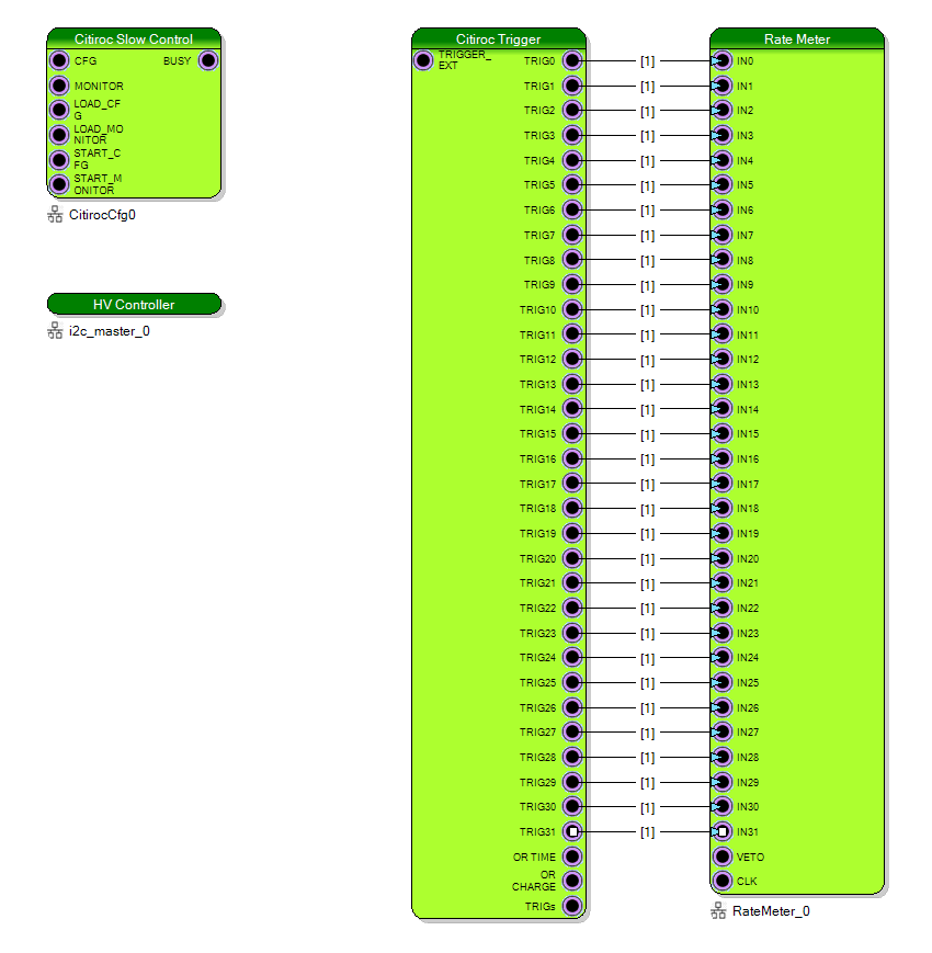
Figure 2: Opening the Citiroc example project
Step 1: Citiroc Slow Control Block
The Citiroc Slow Control block manages ASIC configuration.
Block Configuration
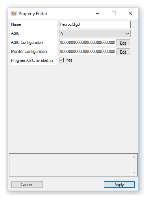
Figure 3: Citiroc Slow Control block properties
Parameters:
- ASIC to configure: Select which Citiroc ASIC (if multiple)
- Default configuration: Configuration applied at boot/reset
- Default monitor config: Monitoring settings
This is a memory-mapped block accessible via USB using SciSDK or Resource Explorer.
Configuration Features
The Citiroc Slow Control block allows you to configure:
- Charge threshold (per channel or global)
- Time threshold (per channel or global)
- Signal polarity (positive/negative)
- Trigger mode and latching
- Channel enable/disable
- Preamplifier gain settings
- Shaping time constants
Step 2: Rate Meter Blocks
Each processing channel measures the trigger rate from one ASIC output.
Rate Meter Implementation
Function:
- Each Citiroc trigger output connects to a rate meter
- Rate meter counts transitions (0→1)
- Counter value updated every second
- Uses 160 MHz reference clock for time base
- Rate value stored in a register
- Register mapped to USB for readout
Multi-Channel Operation:
- One rate meter per channel
- All channels measured simultaneously
- Independent threshold settings possible
- Real-time rate updates
The rate meter is automatically mapped on USB as a rate meter device. SDK functions are embedded in the library to implement rate measurement functionality.
Step 3: Memory Mapping
Assign addresses to registers and peripherals.
Memory Map Configuration
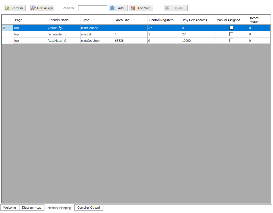
Figure 4: Memory mapping tab
Options:
- Manual address: Enter specific address in “PHY Hex” column
- Auto Assign: Click button to automatically allocate addresses
- Lock address: Check “Manual Assigned” to prevent auto-assign override
Output:
A RegisterFile.json is generated in the project’s library folder during compilation.
Step 4: Compile and Program
Compilation
- Click Compile button in the Home toolbar
- Compilation takes 10-20 minutes
- Upon success, a bitstream is generated
Programming
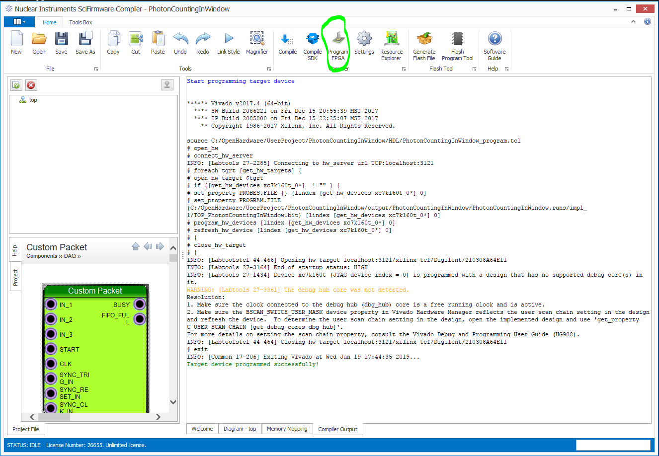
Figure 5: Programming the FPGA
- Connect DT5550W via:
- USB 3.0 (communication)
- JTAG USB (programming)
- Power on the board
- Click Program FPGA in SCI-Compiler
- Wait for “Target device programmed successfully”
Testing with Resource Explorer
Launch Resource Explorer
Resource Explorer allows you to interact with the firmware without writing code.

Figure 6: Opening Resource Explorer
Connect to Board
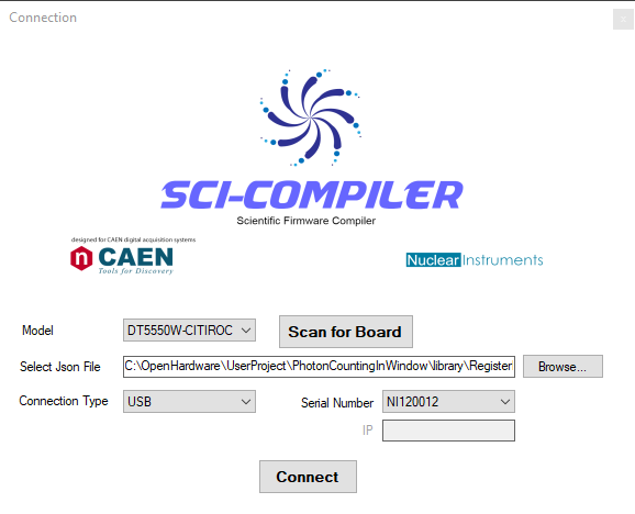
Figure 7: Resource Explorer connection settings
- Select DT5550W-PETIROC from board list
- Click Scan to detect connected boards
- Select correct Serial Number
- Verify JSON file path matches your project
- Click Connect
Discovered Resources
After connection, Resource Explorer enumerates:
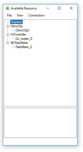
Figure 8: Enumerated resources
- CitirocCfg (ASIC configuration)
- HVcontrol (High voltage controller)
- MCRateMeter (Multi-Channel Rate Meter)
Step 5: Configure High Voltage
Configure the on-board HV generator for SiPM bias.
HV Controller
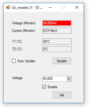
Figure 9: High voltage configuration panel
- Right-click on i2c_master_0 under HVcontrol
- Select Open Configuration
- Set parameters:
- HV Voltage: 54V (adjust based on your SiPM)
- Enable: Check to turn on HV
- Click Set or Update
Monitoring: Click Update to view:
- Current HV voltage
- HV current draw
- SiPM temperature sensor reading
Warning: Ensure SiPM is properly connected before enabling HV. Consult SiPM datasheet for correct bias voltage.
Step 6: Configure Citiroc ASIC
Set discrimination thresholds and operating mode.
Open Citiroc Configuration
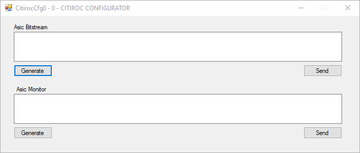
Figure 10: Citiroc configuration interface
Right-click on CitirocCfg → Open Configuration
Generate Configuration
Click Generate to open the full ASIC configuration tool.
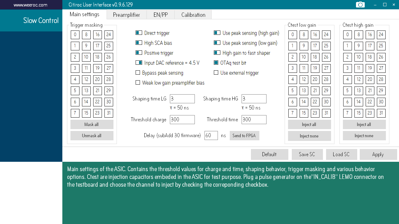
Figure 11: Detailed Citiroc configuration
Recommended Settings for Rate Measurement
Set the following parameters:
| Parameter | Value | Notes |
|---|---|---|
| Charge Threshold | 200 | Lower value = higher threshold (positive polarity) |
| Time Threshold | 300 | Lower value = higher threshold (positive polarity) |
| Polarity | Positive | Match SiPM output polarity |
| Trigger Latch | Disabled | No latch on trigger |
Important: In positive polarity mode, lower threshold values correspond to higher discrimination levels. This is counter-intuitive but correct for the Citiroc ASIC.
Example Configuration Bitstream
The configuration tool generates a bitstream that can be copied and used in SDK applications:
1110111011101110111011101110111011101110111011101110111011101110111011101110111011101110111011101110111011101110111011101110111011101110111011101110111011101110111011101110111011101110111011101110111011101110111011101110111011101110111011101110111011101110110111111111111111111111111111111111111111111011110000111111101111001111011100000001100000001100000001100000001100000001100000001100000001100000001100000001100000001100000001100000001100000001100000001100000001100000001100000001100000001100000001100000001100000001100000001100000001100000001100000001100000001100000001100000001100000001100000001100000001100000001000100000000000000100000000000000100000000000000100000000000000100000000000000100000000000000100000000000000100000000000000100000000000000100000000000000100000000000000100000000000000100000000000000100000000000000100000000000000100000000000000100000000000000100000000000000100000000000000100000000000000100000000000000100000000000000100000000000000100000000000000100000000000000100000000000000100000000000000100000000000000100000000000000100000000000000100000000000111111110100101100010010110011111111111111011
Apply Configuration
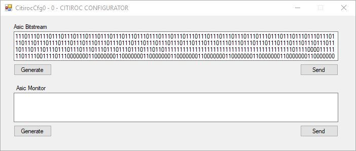
Figure 12: Sending configuration to ASIC
- Click Generate in the configuration tool
- The bitstream is displayed in the text field
- Click Send to program the ASIC
- Configuration is applied to the Citiroc
Step 7: Monitor Trigger Rates
Measure photon count rates in real-time.
Open Rate Meter
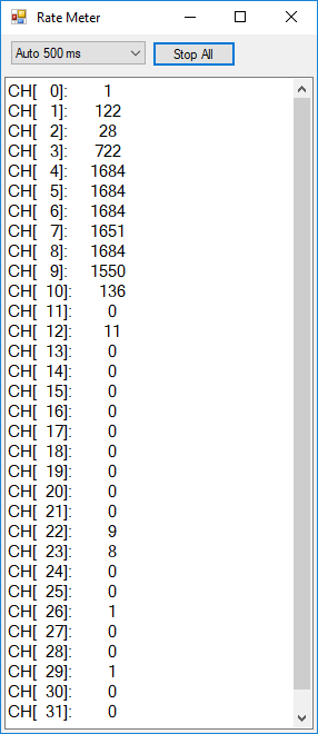
Figure 13: Multi-channel rate meter interface
- In Resource Explorer, expand MCRateMeter
- Right-click and select Open
- Configure display settings:
- Enable Auto Read
- Set update interval
- Click Start
Observe Rate Measurements
Test with Light Pulser:
- Turn on the light pulser
- Adjust light intensity
- Observe rate values for each channel
- Rates update every second
Expected results:
- Channels receiving light show high count rates
- Channels without light show low dark count rates
- Rate varies with light intensity and threshold settings
Adjust Threshold
Experiment with threshold settings:
- Open Citiroc configuration again
- Change Charge Threshold to a different value
- Click Generate and Send
- Observe how rate measurements change
Lower threshold value (e.g., 150) = Higher discrimination → Lower rates, only bright pulses Higher threshold value (e.g., 300) = Lower discrimination → Higher rates, including noise
Understanding the Design
Rate Measurement Principle
SiPM Pulse → Citiroc Discriminator → Trigger (0→1) → Counter → Rate Calculation
The rate meter operates as follows:
- Rising edge (0→1) detected on trigger
- Internal counter increments
- Every 1 second (based on 160 MHz clock):
- Current count is stored as rate value
- Counter is reset to zero
- Next measurement period begins
Rate calculation:
Rate (Hz) = Counter_Value / Time_Period
Rate (Hz) = Counts / 1 second
ASIC Configuration Flow
SCI-Compiler → Generate Bitstream → Slow Control Block → I2C → Citiroc ASIC
Configuration is stored in the ASIC’s internal registers and persists until:
- Power cycle
- Manual reconfiguration
- ASIC reset
High Voltage Control
Resource Explorer → I2C Master → HV Controller IC → DC-DC Converter → SiPM Bias
The DT5550W includes:
- Programmable HV DAC (20-85V range)
- Current monitoring
- Temperature sensing
- Software-controlled enable/disable
Typical Applications
Photon Counting and Rate Measurement
- Dark count characterization of SiPMs
- Single photon detection rate measurement
- Scintillator readout (LYSO, NaI, BGO, CsI)
- Quantum optics experiments
- Background radiation monitoring
Medical Imaging
- PET scanners (Positron Emission Tomography)
- SPECT systems (Single Photon Emission Computed Tomography)
- Gamma cameras
- Coincidence detection for PET
- Time-of-Flight (ToF) PET
High Energy Physics
- Calorimeter readout systems
- Particle tracking detectors
- Timing detectors (Cherenkov, ToF)
- Trigger systems
- Cosmic ray detection
Environmental Monitoring
- Radiation detection and counting
- Dose rate measurement
- Spectroscopy with scintillators
- Air quality monitoring (radioactive particles)
Advanced Topics
Multi-ASIC Configurations
DT5550W supports up to 4 Citiroc ASICs (128 channels total):
- Each ASIC configured independently
- Shared HV distribution
- Individual trigger outputs per channel
- Synchronized readout across all ASICs
- Aggregate rate measurement capability
Time Measurement
Citiroc provides both charge and time outputs:
- Use Oscilloscope block to capture analog outputs
- Implement TDC for precise timing
- Measure Time-over-Threshold (ToT) for energy
- Calculate Time-of-Arrival (ToA) for coincidence
- Build Coincidence logic between channels
Energy Measurement
Add processing blocks for spectroscopy:
- Charge Integration (QDC) for energy measurement
- Spectrum block for MCA functionality
- Baseline restoration for stability
- Pile-up rejection for high rates
- Peak detection algorithms
Advanced Rate Meter Features
Enhance rate measurement capabilities:
- Gated counting (count only during specific periods)
- Prescaling for very high rates
- Integration time adjustment
- Statistical analysis (mean, variance)
- Histogram of rate values over time
List Mode Acquisition
Record event-by-event data:
- Timestamp per trigger
- Charge value
- Time value
- Channel ID
- Store in List endpoint for streaming to PC
- Offline rate analysis with full data
Troubleshooting
No Counts Observed
Problem: Rate meters show zero on all channels
Solutions:
- Verify light pulser is on and fiber connected
- Check HV is enabled and at correct voltage
- Ensure ASIC configuration was sent successfully
- Lower threshold (increase threshold value in positive mode)
- Verify SiPM is properly installed and connected
- Check for proper ASIC power supply
All Channels Showing High Rates
Problem: Excessive count rate on all channels
Solutions:
- Check for light leaks in dark box
- Raise threshold (decrease threshold value)
- Reduce HV to lower SiPM gain
- Check for electrical noise/crosstalk
- Verify trigger latch is disabled
- Inspect for oscillations in ASIC output
Unstable Rate Measurements
Problem: Rate values fluctuate significantly
Solutions:
- Check temperature stability (affects SiPM gain)
- Verify HV voltage is stable
- Increase measurement integration time
- Check for intermittent connections
- Shield from electromagnetic interference
- Verify reference clock is stable
HV Not Stable
Problem: HV voltage fluctuates or doesn’t reach setpoint
Solutions:
- Check SiPM load (current draw)
- Verify board power supply is adequate
- Ensure temperature is stable
- Check for short circuits on SiPM connections
- Reduce HV current limit if needed
ASIC Configuration Fails
Problem: Cannot send configuration to Citiroc
Solutions:
- Verify firmware is programmed correctly
- Check USB connection
- Restart Resource Explorer
- Try manual configuration via registers
- Check I2C bus connections
- Verify ASIC power supply
Rate Meter Not Updating
Problem: Rate values frozen or not updating
Solutions:
- Verify reference clock is running (160 MHz)
- Check firmware compiled correctly
- Restart Resource Explorer connection
- Verify rate meter is started
- Check USB communication bandwidth
Summary
This tutorial covered DT5550W Citiroc rate measurement:
| Topic | Covered |
|---|---|
| Hardware setup | SiPM, dark box, light pulser configuration |
| Firmware design | Citiroc Slow Control, rate meters |
| ASIC configuration | Thresholds, polarity, trigger mode |
| HV control | Bias voltage, monitoring, safety |
| Rate measurement | Multi-channel rate meter, real-time monitoring |
| Testing | Resource Explorer, rate readout |
| Troubleshooting | Common issues and solutions |
Next steps:
- Experiment with different SiPM types and bias voltages
- Add energy and timing measurements
- Implement coincidence logic between channels
- Develop custom SDK applications with SciSDK
- Explore multi-ASIC configurations (up to 128 channels)
- Build list-mode acquisition for detailed analysis
- Create histograms and statistical analysis
Key advantages of DT5550W with Citiroc:
- Complete system for SiPM readout without HDL programming
- Multi-channel rate measurement (32 channels per ASIC)
- Flexible configuration via graphical interface
- Real-time monitoring with Resource Explorer
- High performance with low noise and precise timing
- Scalable up to 128 channels with 4 ASICs