
TM Splitter
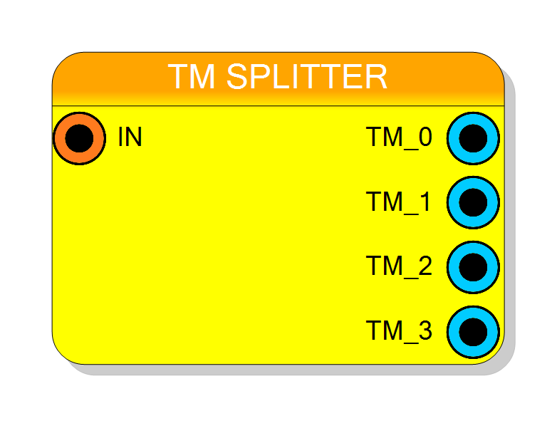
Splits a single time-multiplexed (TM) bus into multiple independent std_logic_vector signals. Takes a TM input and separates each TM phase into its own scalar output. Supports TM factors from 2 to 32. Pure combinational logic with zero latency. Inverse operation of TM Packer.
Introduction
This block splits a single time-multiplexed (TM) bus into multiple independent scalar signals. It is the inverse operation of the TM Packer, extracting each TM phase into a separate output.
The operation is purely combinational with zero clock latency:
$$ \mathrm{TM}_i = \mathrm{IN}[W \times (i+1) - 1 : W \times i], \quad i = 0 \ldots N-1 $$
where $W$ is the word size and $N$ is the TM factor.
Pin Description
Input TM bus, always TM. Width: Word Size × TM Factor TM Factor: Configurable (2 to 32)
Bit layout: Phase i = IN[(i+1)×W-1 : i×W]
N independent scalar output signals (where N = TM Factor). Each output: std_logic_vector of width = Word Size Pin names: TM_0, TM_1, TM_2, …, TM_{N-1}
Output is combinational (zero latency). TM_i = IN[(i+1)×W-1 : i×W]
Properties
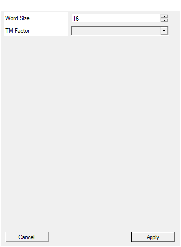
Set the size in bit of word in the input/output
Width in bits of each TM phase (1 to 16384 bits). All output signals will have this same width. Total input width = Word Size × TM Factor.Default: 16
Range: 1 – 16384
Select the TM Factor of the input
Number of TM phases (2 to 32). This determines how many output pins (TM_0 through TM_{N-1}) are created.Default: 4
Options: 2 4 8 16 32
Functional description
The TM Splitter extracts N independent scalar outputs from a single TM bus. Each TM phase becomes one output signal.
Splitting operation
For a TM factor of $N$ and word size $W$:
$$ \mathrm{TM}_i = \mathrm{IN}[(i+1)W - 1 : iW], \quad i = 0 \ldots N-1 $$
In bit notation:
- Phase 0 (TM_0) ← bits $[W - 1 : 0]$
- Phase 1 (TM_1) ← bits $[2W - 1 : W]$
- Phase $i$ (TM_i) ← bits $[(i+1)W - 1 : iW]$
- Phase N-1 (TM_{N-1}) ← bits $[NW - 1 : (N-1)W]$
Total input width: $W \times N$ bits
Example with TM Factor = 4, Word Size = 16
A 64-bit TM input split into four 16-bit outputs:
TM input (64 bits): $$ \mathrm{IN}[63:0] = \texttt{0xDEF0_9ABC_5678_1234} $$
Extracted outputs:
- TM_0 = IN[15:0] = 0x1234
- TM_1 = IN[31:16] = 0x5678
- TM_2 = IN[47:32] = 0x9ABC
- TM_3 = IN[63:48] = 0xDEF0
Output characteristics
- All output signals have the same width (Word Size property)
- Number of outputs equals the TM Factor property
- Each output is an independent scalar std_logic_vector
Signal naming
The component creates N output pins named:
- TM_0, TM_1, TM_2, …, TM_{N-1}
Each output pin is a scalar std_logic_vector of width $W$.
Timing
The component is purely combinational with zero latency:
| Property | Latency (clock cycles) |
|---|---|
| TM Splitter | 0 |
All outputs are available immediately in the same clock cycle as the input.
Typical use cases
- Extracting individual channels from a TM data stream
- Converting TM processing results back to scalar signals
- Interfacing TM blocks to scalar output components
- Data stream demultiplexing for individual channel access
Important notes
- Output order: TM_0 comes from LSBs, TM_{N-1} from MSBs
- No clock required - purely combinational wiring
- Inverse operation: use TM Packer to pack scalar signals
- Input must be connected for successful compilation