
PILEUP REJECT
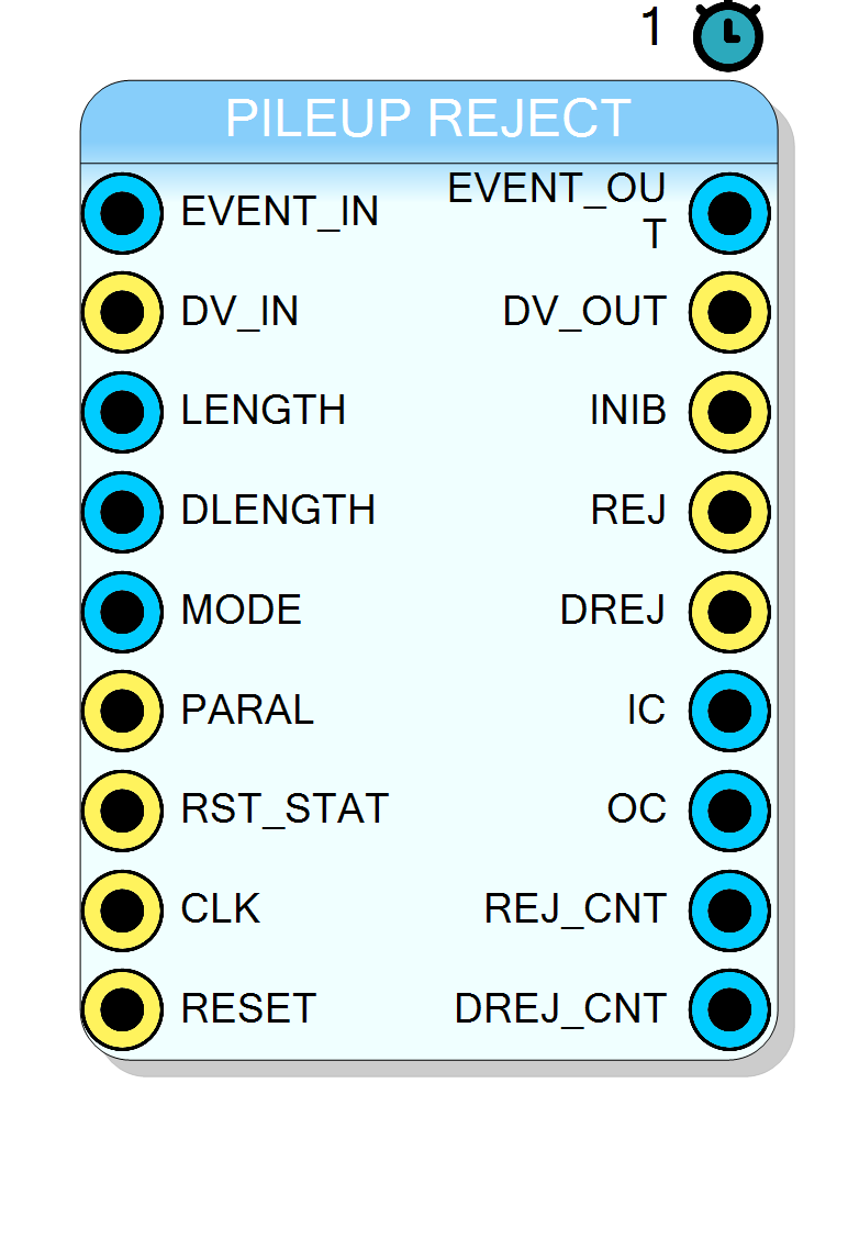
Configurable pile-up rejection IP core with selectable operating modes. Compared to the Simple Pile-up Rejector, this version introduces the MODE pin that dynamically switches between By-pass, Classic and Double-pulse suppression algorithms, providing extended statistics and finer control on the inhibition window.
Introduction
The Pileup Rejector monitors a stream of digitised events and suppresses
events that arrive too close in time, preventing spectral distortion caused
by pile-up. Three algorithms can be selected at run-time through the
MODE pin:
| MODE | Behaviour | Typical use-case |
|---|---|---|
0 |
By-pass – pure wire-through, no dead-time applied. | Baseline measurements / debug |
1 |
Classic single-event inhibition – a fixed dead-time LENGTH |
|
| is started after every accepted event. | Standard spectroscopy | |
2 |
Double-pulse suppression – two nested windows are generated: | |
LENGTH (single) and DLENGTH (double). A second event inside the double |
||
window is tagged as double-reject (DREJ). |
High-count-rate detectors |
A dedicated statistics engine keeps track of inputs, outputs and rejected events in real time.
Pin Description
BITSIZE).Sample is captured on the rising edge of
CLK when DV_IN=1.
EVENT_IN.Must be a one-clock-wide pulse. A rising edge increments
IC.
0: By-pass1: Classic single inhibit2: Double-pulse suppressionOther values are reserved and treated as MODE 0.
This pin is absent in the Simple Pile-up Rejector; its addition is the main functional difference between the two IPs.
0 – inhibition window counts down continuously.1 – every new event restarts the counter (pile-up tolerant).
When asserted, counters
IC, OC, REJ_CNT, DREJ_CNT are cleared
in one clock cycle.
BITSIZE).Valid when
DV_OUT=1.
EVENT_OUT. One-clock-wide.
DLENGTH expires.
$STAT_SIZE-bit Input Counter – number of DV_IN pulses since the
last RST_STAT.
$STAT_SIZE-bit Output Counter – number of DV_OUT pulses since
the last RST_STAT.
$STAT_SIZE-bit Single Reject Counter – cumulative sum of REJ
pulses.
$STAT_SIZE-bit Double Reject Counter – cumulative sum of DREJ
pulses.
Properties
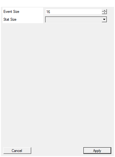
This parameters sets the number of bits for the Input and Output Event size
Width (in bits) ofEVENT_IN and EVENT_OUT.Changing this parameter regenerates the RTL and scales resource usage almost linearly. Accepted range: 1 – 1024 bit.
Default: 16
This parameters sets the number of bits for the statistical counters
Width of the internal statistical counters (IC, OC, REJ_CNT,
DREJ_CNT). Choose the minimal width that avoids overflow during the
expected acquisition time to save area.
Default: 32
Options: 16 32 48 64
Functional principle
Let the arrival times of the $n$-th and $(n+1)$-th events be $t_n,;t_{n+1}$ and define the user–programmable inhibition windows
$$ T_\text{1} = \texttt{LENGTH}, \qquad T_\text{2} = \texttt{DLENGTH};(;T_2 \ge T_1;). $$
The decision logic is
$$ \text{Accept} = \begin{cases} \text{true} & \text{if } (t_{n+1}-t_n) \ge T_\text{act}, \ \text{false} & \text{otherwise}, \end{cases} $$
with
$$ T_\text{act} = \begin{cases} 0 & \text{MODE}=0,\ T_1 & \text{MODE}=1,\ T_2 & \text{MODE}=2 \land (t_{n+1}-t_n)<T_1,\ T_1 & \text{MODE}=2 \land (t_{n+1}-t_n)\ge T_1.\ \end{cases} $$
A programmable parallisable flag (PARAL) further decides whether each
incoming event extends the current dead-time (PARAL=0) or merely restarts
it (PARAL=1).
Statistics
The core integrates four free-running counters:
- $IC$: Input Count
- $OC$: Output Count
- $REJ_CNT$: Single rejects
- $DREJ_CNT$: Double rejects
All counters are $STAT_SIZE-bit wide and can be cleared on-line by
asserting RST_STAT.
Timing
For MODE 0 and MODE 1 the latency is one clock cycle from the rising
edge of DV_IN to DV_OUT.
In MODE 2 the latency becomes data-dependent and can span
$$ 1 + \left\lceil\frac{DLENGTH}{f_\text{CLK}^{-1}}\right\rceil $$
clock cycles in the worst case, because the event is held in an internal
buffer until DLENGTH expires.
MODE 0 / MODE 1 – Fixed latency (1 clock cycle)
MODE 2 – Data-dependent latency (event held until DLENGTH expires) - no pileup
MODE 2 – Data-dependent latency (event held until DLENGTH expires) - pileup
Typical application
In high-count-rate gamma spectroscopy the double-pulse mode (MODE 2) reduces spectrum distortion while keeping throughput high.
-
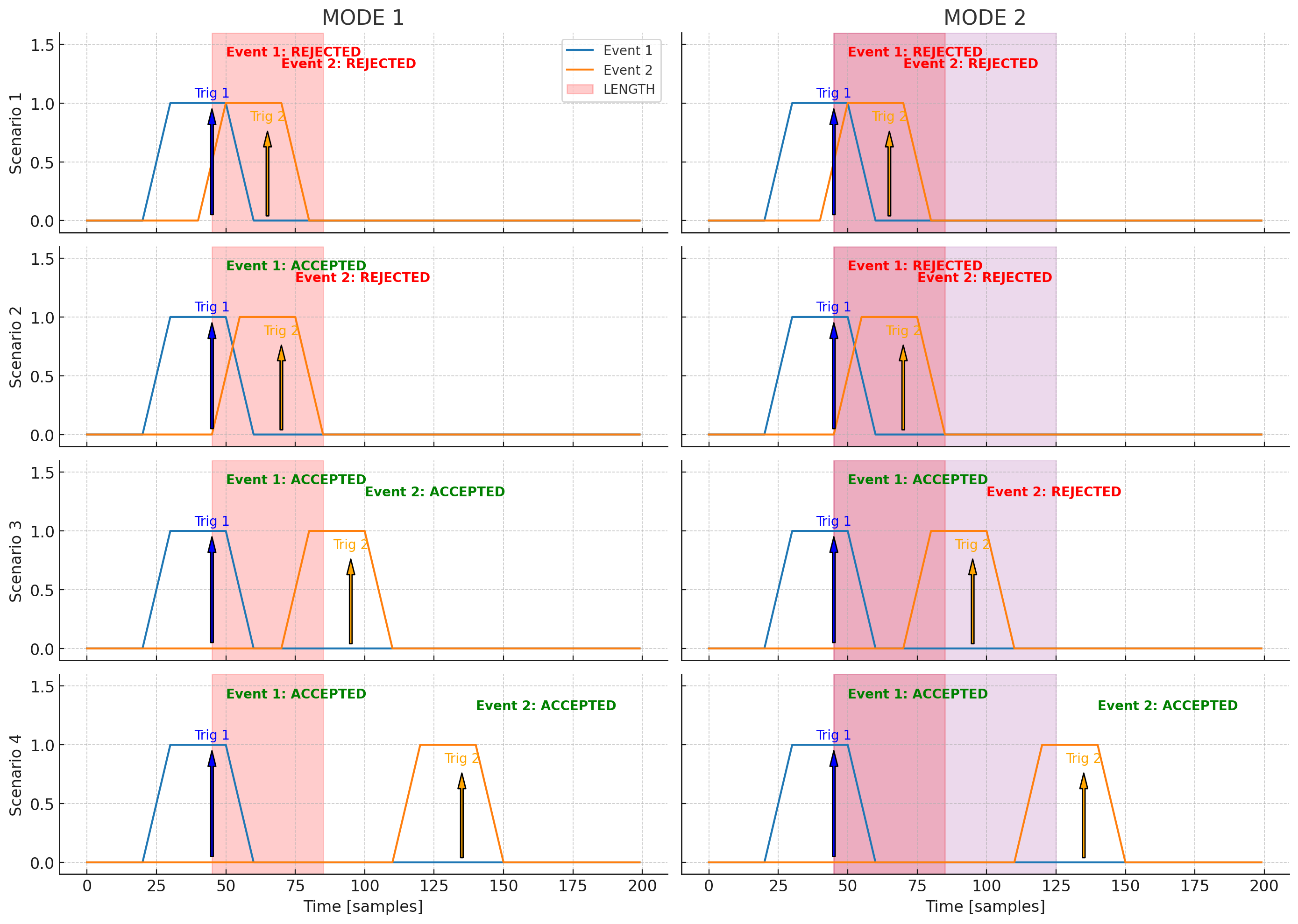
Inhibition windows are shown as:
- 🔴
LENGTH= red shaded area - 🟣
DLENGTH= purple shaded area (only for MODE 2)
- 🔴
-
Triggers are marked with vertical arrows.
-
Acceptance status is shown with green/red labels next to each event.
| Scenario | Description | MODE 1 | MODE 2 |
|---|---|---|---|
| 1 | Events very close | ❌ Both rejected | ❌ Both rejected |
| 2 | Moderate spacing | ✅ Only 1 accepted | ❌ Both rejected |
| 3 | Wider spacing | ✅ Both accepted | ✅ 1st, ❌ 2nd rejected |
| 4 | Fully separated | ✅ Both accepted | ✅ Both accepted |