RF IFFT (compact)
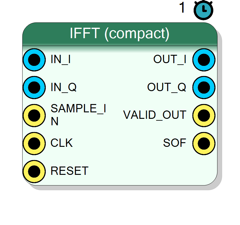
Inverse of the compact FFT: the same self-contained fixed-point radix-2 decimation-in-time core, but with the twiddle sign flipped to +sin (exp(+j...)) and, when Scaled, the per-stage >>1 provides the 1/N normalisation of the inverse DFT. One time-shared complex butterfly, a handful of DSPs regardless of N; input must be gapped (like SeqFIR), and the reconstructed complex sequence is streamed one sample per clock with VALID_OUT and SOF.
Introduction
The IFFT (compact) block computes the inverse discrete Fourier transform, reconstructing a time-domain sequence from a complex spectrum:
x[n] = (1/N) * sum_{k=0..N-1} X[k] * exp(+j*2*pi*k*n / N), n = 0 .. N-1
It is the inverse counterpart of the FFT block and shares the identical hand-written radix-2 decimation-in-time (DIT) core. Only two things differ from the forward transform:
- the twiddle table uses
+sin(W_N^k = cos + j*sin, i.e.exp(+j...)) instead of-sin, and - with Scaled selected, the
>>1performed after every butterfly stage supplies the1/Nnormalisation that the inverse DFT requires.
Everything else - the compact one-butterfly-per-clock architecture, the ping-pong double buffering, the gapped input, and the streamed output - is exactly the same as the FFT block. The area stays tiny (about one time-shared complex multiply) no matter how large N is; the cost of large N is BRAM plus per-frame latency.
Input may be Real (single IN channel, imaginary tied to 0) or
Complex (IN_I / IN_Q); normally you feed the complex spectrum
X[k] on IN_I / IN_Q. The output is the complex reconstructed sequence
(OUT_I / OUT_Q), N samples, streamed one per clock with VALID_OUT
high and SOF pulsing on sample 0.
Visual designer
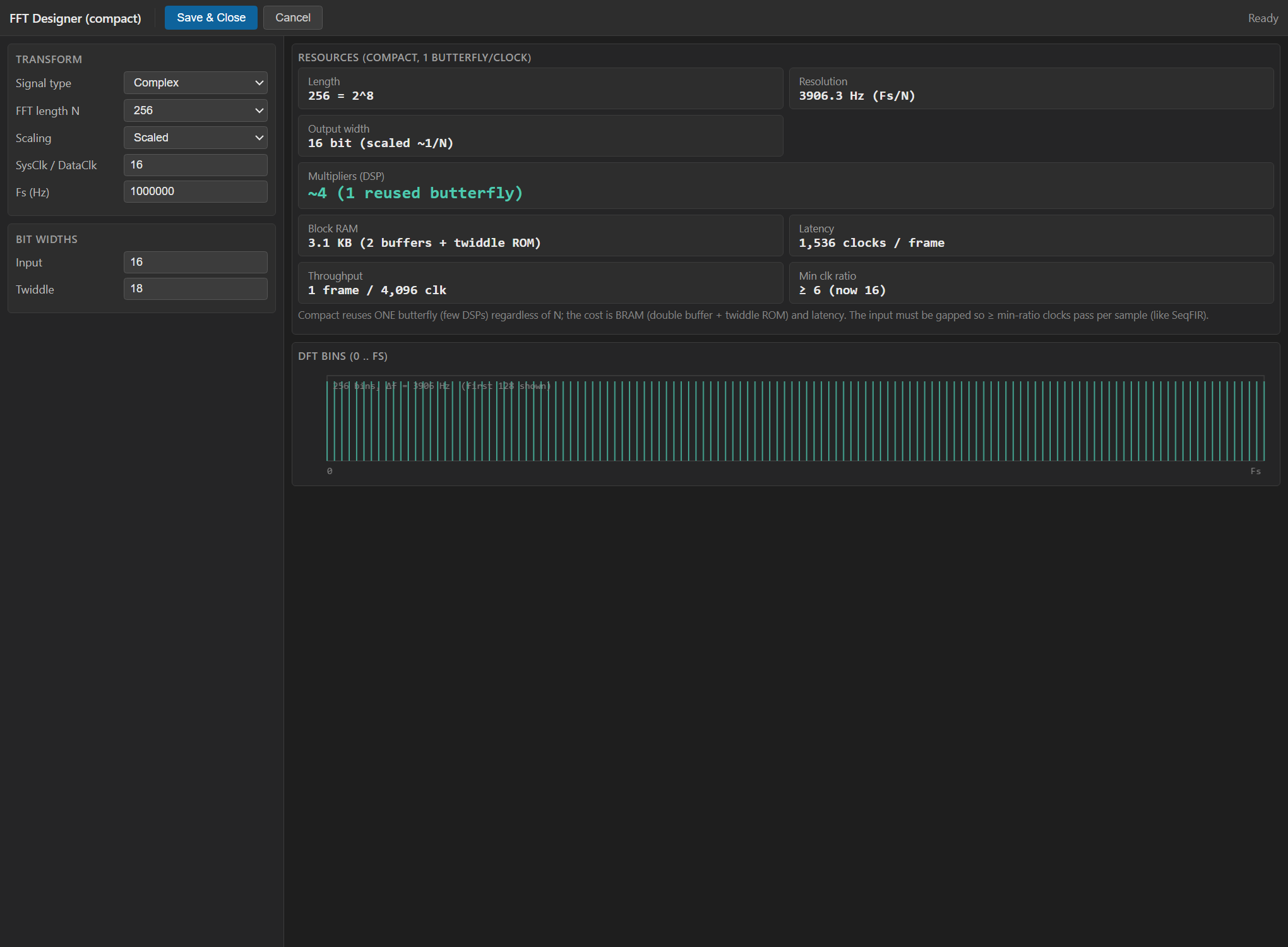
This block uses the same custom WebView2 designer as the FFT (opened in IFFT mode) instead of the standard property grid. Double-click the block to open the FFT Designer, where you choose:
- Signal Type - Real or Complex input.
- FFT Length N - the transform size (power of 2,
Fs/Nbin spacing). - Scaling - Scaled (
>>1per stage, which here gives the1/Ninverse-DFT normalisation and a bounded output) or Unscaled (full bit growth, un-normalised sum). - Input Bit Width and Twiddle Bit Width.
- SysClk / DataClk - the input gap (system clocks per input sample).
As you edit, the designer shows a live resource estimate (reused
butterfly DSPs, double-buffer + twiddle-ROM BRAM, per-frame latency and
throughput) and flags the SysClk/DataClk field red if it is below the
minimum needed to finish a frame in time. It also plots the DFT bins
across 0 .. Fs with the resolution Fs/N. Fs is entered in the
designer only for these estimates; it is not a hardware pin. On save, the
chosen values are written back to the block properties and used to
synthesise the core.
For the forward transform see Component_FFT (FFT).
Pin Description
X[k] (present only
when Signal Type = Complex). Signed, InputSize bits.
X[k]
(present only when Signal Type = Complex). Signed, InputSize
bits.
SysClk/DataClk clocks. N strobes fill one frame.
InputSize + 4 scaled,
InputSize + log2(N) + 2 unscaled).
Properties
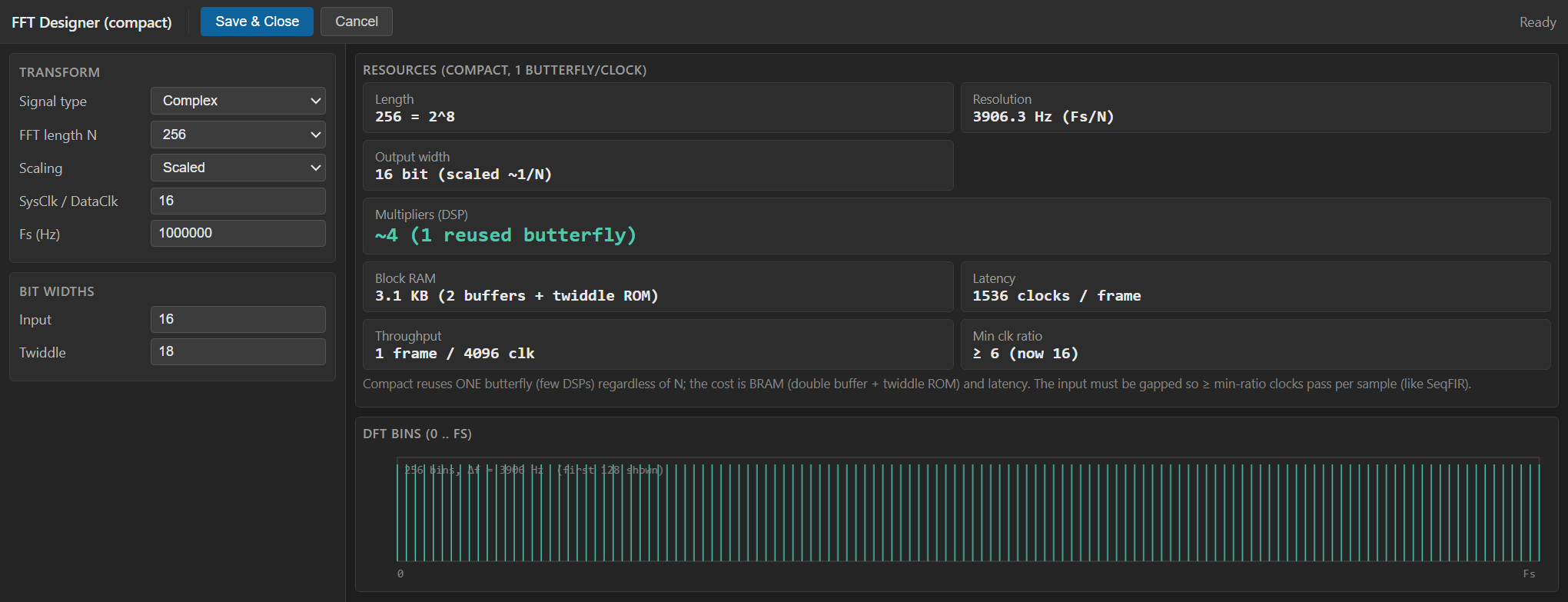
Real: one input channel (imag=0). Complex: I/Q input.
Input format. Real exposes a singleIN channel (imaginary tied
to 0); Complex exposes IN_I / IN_Q (the usual mode for a
complex spectrum). Default Complex.
Default: Complex
Options: Real Complex
Transform size (power of 2). Frequency resolution = Fs/N.
Transform size N (power of 2: 8, 16, 32, … 4096). Sets the number of bins/samples, the buffer/twiddle BRAM, and the per-frame latency. Default 256.Default: 256
Options: 8 16 32 64 128 256 512 1024 2048 4096
Bit width of the input sample(s) (signed).
Bit width of each signed input sample. Range 4 to 32, default 16.Default: 16
Options: 4 5 6 7 8 9 10 11 12 13 14 15 16 17 18 19 20 21 22 23 24 25 26 27 28 29 30 31 32
Bit width of the cos/sin twiddle factors.
Bit width of the cos/sin twiddle factors (12, 14, 16, 18 or 20). Wider twiddles lower the numerical noise floor at the cost of a larger twiddle ROM and wider multipliers. Default 18.Default: 18
Options: 12 14 16 18 20
Scaled: »1 each stage (bounded output, ~1/N). Unscaled: full bit growth (+log2 N bits).
Scaled:>>1 after every butterfly stage - this supplies the
inverse-DFT 1/N normalisation and keeps the output bounded (width
InputSize + 4). Unscaled: no per-stage shift, so the 1/N is
not applied and the datapath carries full bit growth (width
InputSize + log2(N) + 2). Default Scaled.
Default: Scaled
Options: Scaled Unscaled
System clocks per input sample. Must be >= log2(N)/2 + 2 (one butterfly per clock).
SysClk / DataClk - the number of system clocks per input sample (the input gap). Must be>= floor(log2(N)/2) + 2 so the compact core
finishes a frame in time; the plugin errors at compile if it is too
low. Values 4, 8, 16, 32, 64, 128, 256. Default 16.
Default: 16
Options: 4 8 16 32 64 128 256
Config produced by the FFT Designer.
Hidden JSON configuration produced by the FFT Designer (WebView2, IFFT mode). Not edited directly; it mirrors the properties above and is regenerated each time you save the designer.Usage
Inverse radix-2 DIT algorithm
The IFFT is computed exactly like the FFT (in-place, three phases) but with the conjugate twiddle sign:
-
Bit-reversal permutation of the N input (spectrum) samples.
-
log2(N)butterfly stages,N/2radix-2 butterflies each:t = W_N^k * b a' = a + t b' = a - t -
Output of the N reconstructed time samples in natural order.
For the inverse transform the twiddle is
W_N^k = cos(2*pi*k/N) + j*sin(2*pi*k/N) (exp(+j...)). The plugin
generates the same k = 0 .. N/2-1 twiddle ROM as the FFT but with
WI = +sin (the FFT uses WI = -sin); WR = cos is identical. This
single sign flip is what turns the forward core into the inverse one.
1/N normalisation via Scaled
The inverse DFT carries a 1/N factor. The core does not have a separate
divider: with Scaled it shifts the datapath right by 1 after each of
the log2(N) stages, and 2^-log2(N) = 1/N, so the output is correctly
normalised and bounded. With Unscaled the 1/N is not applied - you
get the raw (un-normalised) inverse sum with full bit growth, and must
divide by N downstream if you need true amplitude.
Compact one-butterfly-per-clock architecture
Identical to the FFT block. Two ping-pong frame buffers overlap load / compute / output:
- Load - each
SAMPLE_INstrobe stores one input sample (bit-reversed) into the load buffer; N strobes fill a frame. - Compute - one radix-2 butterfly per system clock; a frame is
(N/2) * log2(N)butterflies. - Output - the N samples are streamed one per clock with
VALID_OUThigh andSOFon sample 0.
Only one complex butterfly (about four real multipliers) is in the fabric, time-shared across all stages, so area is roughly constant in N.
Gapped input and the SysClk/DataClk ratio
As with the FFT, compute is serial, so the input must be gapped: strobe
SAMPLE_IN at most once every SysClk / DataClk system clocks. The
plugin requires
SysClk / DataClk >= floor(log2(N) / 2) + 2
and errors at compile otherwise (the designer flags it live). This ensures
the (N/2)*log2(N)-clock compute plus N-clock output finish inside the
N * ratio load window. Frame throughput is one frame every
N * (SysClk/DataClk) system clocks.
Bit widths
All state is carried in data_t = InputSize + StateGrowth bits
(StateGrowth = 4 scaled / log2(N)+2 unscaled); twiddle products use
InputSize + StateGrowth + TwiddleBits + 1 bits before the
>> (TwiddleBits-2) arithmetic shift. Output port width:
- Scaled:
InputSize + 4bits (normalised, bounded). - Unscaled:
InputSize + log2(N) + 2bits (un-normalised, full growth).
Real vs Complex input
- Complex -
IN_I/IN_Qcarry the spectrumX[k]; the general (complex) inverse is produced. This is the normal mode. - Real - only
INis present, imaginary forced to 0. Use only when the spectrum is purely real. The core still streams a full complex output.
Frequency / sample resolution (DFT bins)
bin spacing = Fs / N
bin k = k * Fs / N (k = 0 .. N-1; k > N/2 = negative freqs)
Reset
RESET is the HLS synchronous reset (ap_rst); it clears the frame
counters and processing state so the next frame starts clean.
Typical applications
- Frequency-domain to time-domain reconstruction after spectral processing.
- Fast convolution / correlation back-end paired with the FFT block (multiply spectra, then IFFT).
- OFDM-style symbol synthesis from bin values.
Resources & Timing
-
Latency: Per-frame, pipelined across ping-pong buffers: ~
N(load) +(N/2)*log2(N)(compute, one butterfly per clock) +N(output stream) system clocks. Dominated by the(N/2)*log2(N)compute term for large N. -
Throughput: One frame every
N * (SysClk/DataClk)system clocks; one output sample per clock during the N-clock output phase. Input is gapped (one sample everySysClk/DataClkclocks), not one per clock.
Same compact radix-2 DIT core as the FFT block, twiddle ROM built with
+sin for the inverse transform and the Scaled >>1-per-stage giving the
1/N normalisation. Only one time-shared complex butterfly (~4 DSP
multipliers) is instantiated regardless of N. BRAM holds two N-point
ping-pong buffers (re+im) plus the N/2-entry twiddle ROM. Area is
roughly constant in N; large N costs BRAM and latency. All ports use the
ap_none / ap_ctrl_none free-running interface (no AXI handshake).