
Round Robin Arbiter (FIFO)
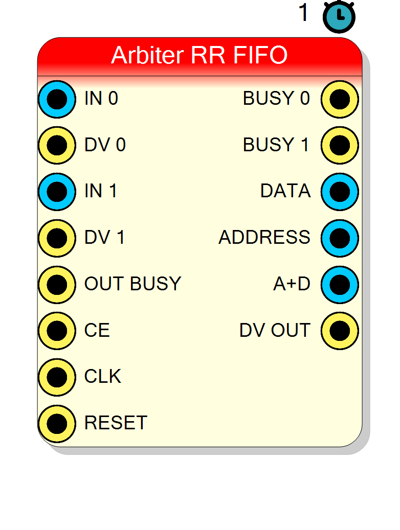
Multiplexes multiple data channels onto a single output with integrated input FIFOs. Provides buffering and backpressure for each input channel independently.
Introduction
The Round Robin Arbiter (FIFO) is an enhanced version of the standard Round Robin Arbiter with integrated input FIFOs for each channel. This eliminates the need for external FIFOs and provides automatic buffering and backpressure handling.
This block is ideal when:
- Input sources cannot be paused (e.g., ADC streams)
- Data arrives in bursts that need buffering
- You need per-channel flow control without external components
Pin Description
Backpressure output for channel x.
- HIGH (1): Internal FIFO is nearly full, stop sending
- LOW (0): FIFO has space, continue sending Connect to flow control of upstream data source. On an unserved channel (x >= Served inputs) it is permanently 0, i.e. “never busy” - see the warning in the description.
[ADDRESS (8 bits)] [DATA (N bits)]
Width = 8 + Data Size.
Recommended output for downstream connection.
Properties
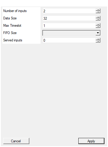
Set the number of input to the arbiter
Number of input channels declared. This is what fixes the pin count and the channel numbering seen on ADDRESS / A+D; it is the count the rest of the design must agree with. Range: 1 to 128, default 2.Default: 2
Range: 1 – 128
Set the number of bits of the input data. Should be common for all inputs
Width of each data channel in bits. Range: 1 to 2048, default 32.Default: 32
Range: 1 – 2048
Specify the number of clock cycles as a timeout for the input before switching to the next channel.
Maximum samples read from one channel before switching. Range: 1 to 65535, default 1.Default: 1
Range: 1 – 65535
Number of word can be stored in the FIFO
Depth of each input FIFO in words. Larger values handle more bursty data but use more BRAM. Available values: 32, 64, 128, 256, 512, 1024, 2048, 4096, 8192, 16384, default 32.Default: 1
Options: 32 64 128 256 512 1024 2048 4096 8192 16384
Number of inputs the arbiter actually serves, out of the declared ‘Number of inputs’. Inputs above this count keep their pins (and therefore the channel numbering on ADDRESS / A+D) but get NO FIFO: whatever is written on them is discarded, the arbiter never polls them and their BUSY output is tied to 0. Leave it at 0 - or set it to ‘Number of inputs’ or more - to serve every declared input.
Number of declared channels the arbiter actually serves. Channels from this index up keep their pins but get no FIFO, are never polled by the round robin rotation, and hold their BUSY output at 0. 0 (the default) - or any value greater than or equal to InputCount - means “serve them all”, which is exactly the behaviour this block had before the property existed; projects saved earlier read back as 0 and are unaffected. The output format (8 bit ADDRESS,8 + Data Size A+D) never depends on this value.
Range: 0 to 128, default 0.
Default: 0
Range: 0 – 128
Usage
Difference from Standard Arbiter
| Feature | Standard Arbiter | FIFO Arbiter |
|---|---|---|
| Input interface | RD/DV (pull from external FIFO) | WE/BUSY (push to internal FIFO) |
| Buffering | External FIFOs required | Built-in per-channel FIFOs |
| Backpressure | RD signal to external FIFO | BUSY signal to data source |
| Resource usage | Minimal | Higher (uses BRAM for FIFOs) |
Why Use the FIFO Version?
The FIFO version is preferable when:
- Sources cannot wait: ADCs, deserializers, and other streaming sources need somewhere to put data immediately
- Burst handling: Input data arrives in bursts; FIFOs absorb peaks
- Simpler integration: No need to instantiate and connect separate FIFOs
- Independent backpressure: Each channel has its own BUSY signal
Internal Architecture
Each input channel has a dedicated async FIFO (xpm_fifo_async):
Channel 0: IN_0 ──►[FIFO 0]──►┐
DV_0 ──►(WE) │
BUSY_0◄─(FULL) │
▼
Channel 1: IN_1 ──►[FIFO 1]──►┬──► Arbiter ──► DATA/ADDRESS/A+D
DV_1 ──►(WE) │ ▲
BUSY_1◄─(FULL) │ (timeslot)
│
Channel N: IN_N ──►[FIFO N]──►┘
DV_N ──►(WE)
BUSY_N◄─(FULL)
Declaring More Inputs Than You Serve (Served inputs)
Number of inputs declares the interface: how many IN/DV/BUSY pin triplets the block shows, and therefore which channel numbers can appear on ADDRESS / A+D. Served inputs declares the population: how many of those channels actually get a FIFO and a place in the rotation.
Leave Served inputs at 0 and everything behaves exactly as before: all declared inputs are served. Set it to a smaller number and the inputs from that index up become unserved:
Served input (i < Served) |
Unserved input (i >= Served) |
|
|---|---|---|
| Input FIFO | one xpm_fifo_async, FIFO Size deep |
none - no BRAM, no logic |
| IN i / DV i pins | present, written into the FIFO | present, silently discarded |
| BUSY i output | FIFO prog_full | tied to 0 forever |
| Round robin rotation | polled in turn | never entered - costs no arbitration cycle |
ADDRESS value i |
can be produced | can never be produced |
The unserved inputs still occupy their rows on the block; their captions are marked
(off).
This is where the property pays for itself: each unserved channel saves a whole
FIFO Size x Data Size FIFO. Declaring 16 channels and serving 4 costs the BRAM of 4,
not 16.
Careful - an unserved BUSY reads as “keep sending”. BUSY is active high (1 = FIFO nearly full, stop), so tying it to 0 tells the upstream source it is always free to push, and everything it pushes is dropped on the floor. That is the intended behaviour (an unserved channel is one that has no source wired to it), but if you do leave a live producer connected to an unserved input, it will not be throttled and it will not be told that its data is being lost.
The output format never changes. ADDRESS is always 8 bit and A+D is always
8 + Data Size bits, whatever the declared or served count - a downstream decoder
cannot tell a partial build from a full one by looking at the bus. This is deliberate:
you can raise Served inputs later without re-cutting anything downstream.
Two boundary cases worth knowing:
- Served = 1: the rotation never leaves channel 0. That is the same behaviour as a block declared with a single input - no lock-up, DV OUT keeps flowing, ADDRESS stays 0.
- Served = Number of inputs (or 0): the emitted VHDL is byte for byte the VHDL this block produced before the property existed. Projects saved before it existed read back as 0 and are therefore untouched.
The Timeslot Concept
Like the standard arbiter, the Max Timeslot parameter limits how many consecutive samples are read from one channel before switching.
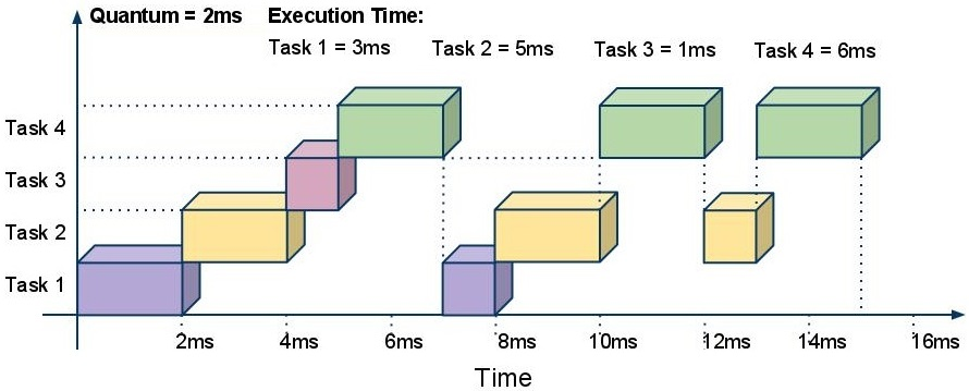
Example with Max Timeslot = 3 and 3 channels:
| FIFO | Content | Samples |
|---|---|---|
| FIFO_0 | A, B, C, D, E | 5 |
| FIFO_1 | X, Y | 2 |
| FIFO_2 | 1, 2, 3, 4 | 4 |
Output sequence:
- A, B, C → switch (timeslot expired)
- X, Y → switch (FIFO empty)
- 1, 2, 3 → switch (timeslot expired)
- D, E → switch (FIFO empty)
- (skip CH1, empty)
- 4 → switch (FIFO empty)
The arbiter automatically:
- Switches when timeslot expires
- Switches when channel FIFO becomes empty
- Skips channels with empty FIFOs
FIFO Depth and Backpressure
The FIFO Size property sets the depth of each input FIFO. Choose based on:
| Use Case | Recommended Size |
|---|---|
| Low-rate sensors | 32-64 |
| Moderate throughput | 128-256 |
| High-rate ADCs | 512-2048 |
| Burst data (scope mode) | 4096-16384 |
When a FIFO fills to ~95% capacity (prog_full threshold = fifolength-5), the corresponding BUSY output goes HIGH, signaling the source to stop sending data.
Understanding the Output Signals
DATA Output
Contains only the data value from the currently selected channel.
ADDRESS Output
Contains the channel number (0 to N-1) as 8 bits, identifying which channel produced the current sample.
A+D (Address + Data) Output
Combines ADDRESS and DATA into a single bus:
A+D = [ADDRESS (8 bits)] [DATA (N bits)]
MSB LSB
This is the recommended output because:
- Channel identification travels with the data
- Single connection to downstream FIFO/endpoint
- Decoding is simple:
channel = A+D >> DataSize
Timing and Latency
The internal FIFOs add latency compared to the standard arbiter:
| Stage | Latency |
|---|---|
| Write to FIFO | 1 clock cycle |
| FIFO read latency | 1 clock cycle |
| Arbiter state machine | 2 clock cycles |
| Total | ~4 clock cycles |
The arbiter state machine:
- s0: Check if current channel FIFO is non-empty AND timeslot > 0
- s0b: Wait 1 cycle for FIFO read latency
- s1: Output data, decrement timeslot, return to s0
Timing Diagram
Handling Backpressure (OUT BUSY)
The OUT BUSY input pauses the entire arbiter:
- When HIGH, the arbiter freezes (no reads from internal FIFOs)
- Internal FIFOs continue accepting data until full
- When LOW, normal operation resumes
Connect to the FULL signal of your downstream FIFO or endpoint.
Practical Example: 4-Channel ADC Readout
ADC_0 ────────► IN_0 DATA ────────► Readout
ADC_VALID_0 ──► DV_0 FIFO
BUSY_0 ──► (optional)
ADC_1 ────────► IN_1 ADDRESS ──────► (decode)
ADC_VALID_1 ──► DV_1
BUSY_1 ──► (optional)
ADC_2 ────────► IN_2 A+D ──────────► USB
ADC_VALID_2 ──► DV_2 Endpoint
BUSY_2 ──► (optional)
ADC_3 ────────► IN_3 DV_OUT ────────► WE
ADC_VALID_3 ──► DV_3
BUSY_3 ──► (optional)
FIFO_FULL ──► OUT_BUSY
Settings:
- Number of inputs: 4
- Data Size: 16 (typical ADC width)
- Max Timeslot: 64 (good for balanced readout)
- FIFO Size: 1024 (handles bursts)
Resources & Timing
-
Latency: ~4 clock cycles
-
Throughput: 1 sample per 3 clock cycles per active channel
Uses one xpm_fifo_async (Xilinx) per SERVED input. BRAM usage = Served inputs x FIFO_SIZE x DATA_SIZE bits - an unserved input costs no BRAM and no rotation cycle, only its pin rows.