
Interpolated Trigger - d'
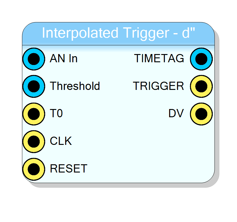
ATI_LINEAR is a sub-sample trigger that detects the zero-crossing of the discrete second derivative of a 16-bit sampled waveform. A 48-bit time-tag is generated with 4-bit sub-sample resolution, together with a single-cycle trigger pulse. The core is fully synchronous and supports time-multiplexed signal streams.
Introduction
ATI_LINEAR implements a linear-interpolated second-derivative trigger suitable for precise time-of-arrival measurements on fast analog pulses (e.g. SiPM, MCP-PMT, diamond detectors).
Let
$$ \begin{aligned} V[n] &= \text{input sample at clock } n,\ d[n] &= V[n]-V[n-3] \qquad; \text{(1st derivative)},\ d_2[n] &= d[n]-d[n-1] \qquad \text{(2nd derivative)}. \end{aligned} $$
A trigger is armed whenever
$$ d_2[n] \ge \mathrm{THR} ;\land; d_2[n-1] < \mathrm{THR}, $$
where THR is the programmable Threshold input.
When the second derivative subsequently changes sign
($d_2[n] < 0$) the exact zero-crossing is found by linear interpolation
$$ x = \frac{-d_2[n-1]}{d_2[n]-d_2[n-1]};;,\qquad 0 \le x < 1, $$
which is internally represented on 4 fractional bits ($x_\text{fixed}= \lfloor 16,x \rfloor$).
The 48-bit output time-stamp is therefore
$$ T_\text{out}= (N_{\text{clk}}\ll4)+x_\text{fixed}, $$
offering a resolution of $T_\mathrm{s}/16$, where $T_\mathrm{s}$ is the sampling period.
Pin Description
Unsigned 16-bit data, sampled at the system clock
{counter[43:0], fraction[3:0]}.Valid only when DV = 1 (one clock cycle).
Usage
Functional overview
ATI_LINEAR is a four-stage finite-state machine:
| State | Action |
|---|---|
| IDLE | Wait for second-derivative arming condition. |
| MEAS1 | Store $(d_2[n-1],d_2[n])$ and raise TRIGGER for one cycle. |
| MEAS2 | Compute fractional delay x. |
| OUTPUT | Deliver 48-bit TIMESTAMP, assert DV, return to IDLE. |
Internally a 44-bit free-running counter timestamp_counter
(incremented every clock) provides the coarse time base.
On each event the counter is concatenated with the 4-bit interpolation
result to form the fine-time tag.
Mathematical background
The trigger exploits the fact that the zero of the second derivative coincides with the peak of a smoothly varying pulse. By delaying the first-difference by three samples, $d[n]$ approximates $\frac{dV}{dt}$ , giving a symmetric estimate of the curvature $d_2[n]$ with good noise rejection.
To minimise timing walk, the discrete points $(n-1,x=0)$ and $(n,x=1)$ are linearly interpolated; because the computation is purely arithmetic it synthesises efficiently in FPGA fabric (18-bit adders/dividers).
Practical use-case
Typical applications include:
- PET or TOF-PET detectors using SiPM arrays.
- Particle-time-of-flight (TOF) counters.
- Laser-range finding or LIDAR TDC pre-processing.
A rule-of-thumb for the threshold is
$$ \mathrm{THR} \approx 5 \sigma_{d_2}, $$
where $\sigma_{d_2}$ is the RMS of the second derivative during baseline.
Timing
-
Latency (CLK domains):
• 1 cycle from threshold crossing to TRIGGER assertion
• 3 cycles from threshold crossing to TIMESTAMP / DV -
Throughput: one sample per clock. Dead time is 3 cycles after a trigger event.