
RF FIR Low-Pass (fixed)
Low-pass FIR filter for a complex I/Q baseband stream with coefficients computed by the plugin from a cutoff-frequency property and baked into the netlist. Typical use: brick-wall the RF image after a mixer to isolate the baseband envelope.
Introduction
The FIR Low-Pass (fixed) block is a direct-form FIR that filters a
complex baseband stream (I and Q share the same set of real coefficients).
The coefficients are computed inside the plugin at design time using a
windowed-sinc method (Hamming window, DC gain normalised to 1) from the
Cutoff (normalised to Fs) property, quantised to CoefSize signed
bits and stored as a NumTaps * CoefSize bit constant in the VHDL. They
are not exposed to the fabric.
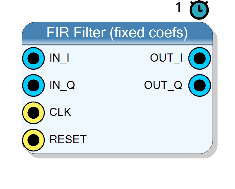
IN_I ─┐ ┌── OUT_I
│ [ FIR ] │
IN_Q ─┘ └── OUT_Q
(h[k] baked in)
For a run-time programmable version see Component_FIRProgrammable.
Pin Description
Properties
Real: one channel. Complex: independent I/Q with the same real coefficients.
Default: Complex
Options: Real Complex
Bit width of each I and Q input sample (signed)
Bit width of each I / Q input sample. Range 4 to 32, default 16.Default: 16
Options: 4 5 6 7 8 9 10 11 12 13 14 15 16 17 18 19 20 21 22 23 24 25 26 27 28 29 30 31 32
Bit width of each coefficient (signed)
Bit width of each signed coefficient. A larger value gives a lower stop-band error floor at the cost of DSP width. Default 16.Default: 16
Options: 8 10 12 14 16 18 20 24
Number of filter taps (filter order = NumTaps - 1). Larger values give sharper roll-off but use more DSPs.
Number of filter taps (filter order =NumTaps - 1). More taps give
a sharper transition band at the cost of DSPs and latency of the
convolution tree. Default 32.
Default: 32
Options: 8 16 24 32 48 64 96 128
Low-pass cutoff frequency expressed as a fraction of the sampling frequency Fs. Range 0..0.5 (Nyquist). Typical baseband filter after a mixer: 0.05 - 0.15.
Low-pass cutoff normalised to the sampling frequency Fs. Valid between 0 and 0.5 (Nyquist). Typical baseband filter after a mixer:0.05 - 0.15. Default 0.1.
Default: 0.1
Options: 0.02 0.05 0.075 0.1 0.15 0.2 0.25 0.3 0.35 0.4
Symmetric: fold linear-phase taps (~N/2 multipliers). Full: one multiplier per tap.
Default: Symmetric
Options: Symmetric Full
Full = full-precision accumulator. InputSat = input width, »shift then saturate. InputShift = input width, MSBs kept.
Default: Full
Options: Full InputSat InputShift
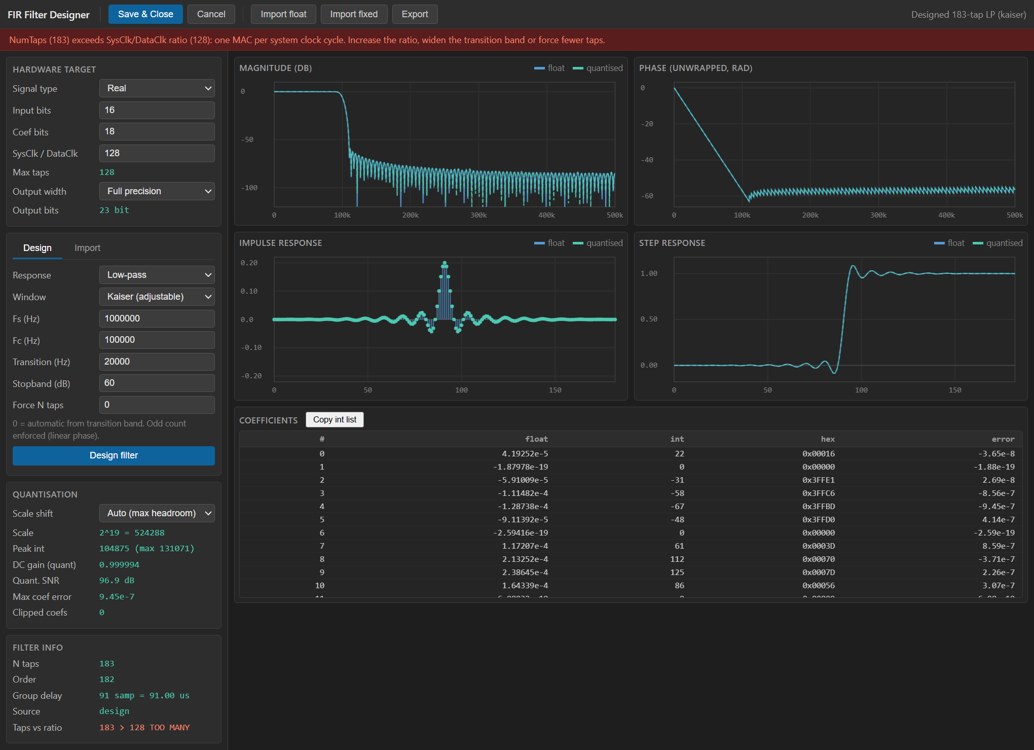
The filter’s spec + quantised coefficients, produced by the FIR Designer.
Usage
Mathematical model
For each channel c in {I, Q} the output at sample n is
y_c[n] = sum_{k=0..NumTaps-1} h[k] * x_c[n-k]
where h[k] is the same set of real coefficients for both channels. This
is exactly what a low-pass baseband filter needs after a complex mixer:
the mixer produces IN_I + j*IN_Q, and the FIR removes the far side of
the spectrum (typically the 2*f_LO image), leaving the base envelope.
Coefficient generation
The plugin computes coefficients using the standard windowed-sinc method:
h_ideal[n] = 2*fc * sinc(2*fc*(n - (N-1)/2))
w[n] = 0.54 - 0.46 * cos(2*pi*n / (N-1)) (Hamming)
h[n] = h_ideal[n] * w[n]
then normalises so that sum h[n] = 1 (unity DC gain) and quantises to
a signed CoefSize-bit integer, scaling by 2^(CoefSize-1) - 1. The
resulting coefficient with the largest absolute value therefore never
overflows the coefficient word width.
Bit widths
Data is treated as signed two’s complement.
IN_I,IN_Q: signedInputSizebits.OUT_I,OUT_Q: signedInputSize + CoefSize + 8bits.
The extra 8 bits allow the accumulator to absorb up to 256 taps without overflow while preserving the full-precision result. Truncate downstream if fewer bits are needed.
Latency and throughput
#pragma HLS PIPELINE II=1: one sample pair per clock.- 1-clock combinational latency (delay-line update + MAC tree).
- All ports use the
ap_noneinterface (no ready/valid handshake).
Reset
RESET is the HLS synchronous reset (ap_rst) and clears the delay
lines.
Typical applications
- Baseband channel-select after a mixer (
Cutoff = channel_BW / Fs). - Anti-aliasing before a rate reducer.
- Envelope extraction for a modulated pulse.
Resources & Timing
-
Latency: 1 clock cycle
-
Throughput: 1 sample per clock (II=1)
Implemented with Vitis HLS. NumTaps DSP48 slices per channel are used for the multiply-accumulate. Because the coefficients are compile-time constants Vivado can optimise constant-zero or +/-1 coefficients away.