
Frame Transfer (2D Distribution)
Transfers multi-channel event data (2D distributions/images) from pixelated sensors to PC. Each frame contains a timestamp, trigger information, and energy values for all channels. Supports AND/OR/External trigger modes and multi-board synchronization.
Introduction
Principle of Operation
The Frame Transfer block transfers multi-channel event data from pixelated sensors or detector arrays to the PC. Each triggered event generates a frame containing:
- 64-bit timestamp
- 64-bit trigger counter
- 64-bit frame counter
- Channel trigger mask
- Energy values for all channels
This is ideal for:
- Imaging detectors (pixelated sensors, CCDs, SiPMs arrays)
- Multi-channel spectroscopy (simultaneous energy readout)
- Event-by-event analysis with timing correlation
- 2D distributions reconstruction
The block can be visualized through Resource Explorer or read programmatically using SciSDK.
SciSDK Documentation: https://nuclearinstruments.github.io/SCISDK/
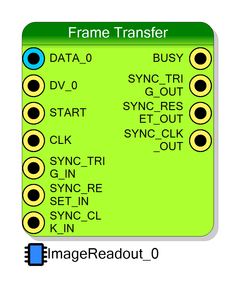
Pin Description
trigger_mode = ext, a rising edge on this
input triggers frame acquisition.
trigger_mode = sync and CONFIG_SYNC[0] = 1.
Properties
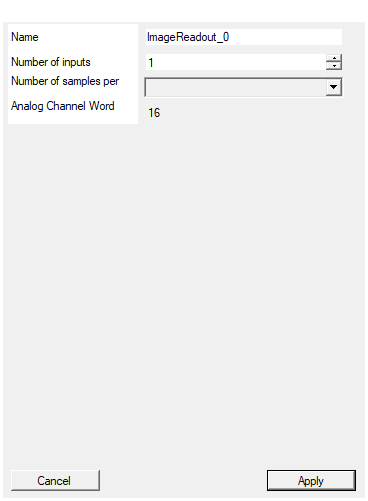
Set the name of the endpoint
Logical endpoint name used in register map. Used in Resource Explorer and SciSDK. Default: ImageReadout_0Default: ImageReadout_0
Set the number of input to the virtual block
Number of input channels (pixels). Range: 1 to 32. Each channel has a DATA and DV input pair. Default: 1Default: 1
Range: 1 – 32
Set the number of samples stored for each acquisition
FIFO buffer depth in frames. Available values: 128, 256, 512, 1024, 2048, 4096. Default: 1024Default: 1024
Options: 128 256 512 1024 2048 4096
Set the analog channel word size in bits
Channel data word size in bits. Fixed at 16 bits. Default: 16Default: 16
Range: 1 – 32
⚙️ Detailed Operation
Data Flow
┌──────────────────────────────────────────────────────────────────────────┐
│ Frame Transfer Data Flow │
│ │
│ DATA_0 ──────►┌────────────────┐ │
│ DV_0 ────────►│ │ │
│ DATA_1 ──────►│ Frame │ ┌─────────────┐ │
│ DV_1 ────────►│ Builder │────►│ FIFO │────► PC │
│ ... │ State Machine │ │ Buffer │ │
│ DATA_n ──────►│ │ │ │ │
│ DV_n ────────►│ │ └─────────────┘ │
│ └────────────────┘ │
│ ▲ │
│ START ──────────────┤ │
│ CE ─────────────────┤ │
│ │ │
│ ┌────┴────┐ │
│ │ BUSY │──► HIGH during frame transfer │
│ └─────────┘ │
└──────────────────────────────────────────────────────────────────────────┘
Frame Builder State Machine
The VHDL implements a state machine that builds frames on trigger events:
┌───────┐ trigger ┌──────────┐ wait done ┌──────────┐
│ IDLE │─────────────────►│WAIT_RUN │─────────────────►│ HEADER0 │
└───────┘ └──────────┘ └──────────┘
▲ │
│ ▼
│ ┌──────────────┐ ┌──────────┐
│ │ SEND_ENERGY │◄───────────────│ HEADER1 │
│ └──────────────┘ └──────────┘
│ │ │
│ all channels │ ▼
└─────────────────────────┘ ... HEADER8
Timing Diagram
Normal Frame Acquisition:
Trigger Modes:
Trigger Logic (from VHDL)
The trigger is generated based on CONFIG_TRIGGER_MODE:
| Mode | Value | Logic | Description |
|---|---|---|---|
| AND | 000 |
AND(DV & MASK) |
All masked channels must be valid |
| OR | 001 |
OR(DV & MASK) |
Any masked channel valid triggers |
| External | 010 |
START input |
External trigger signal |
| Sync | 100 |
SYNC_TRIG input |
Synchronized trigger from another board |
Wait Time
The CONFIG_WAIT register adds delay cycles between trigger detection and energy capture.
This allows late-arriving channels to settle before capture:
Frame Data Structure
Each frame consists of a fixed header followed by channel energy values:
| Word | Content | Description |
|---|---|---|
| 0 | 0xFFFFFFFF |
Header marker (sync word) |
| 1 | 0x12345678 |
Frame identifier |
| 2 | TIMECODE[63:32] | Timestamp high 32 bits |
| 3 | TIMECODE[31:0] | Timestamp low 32 bits |
| 4 | COUNTER_IN[63:32] | Trigger count high (total triggers) |
| 5 | COUNTER_IN[31:0] | Trigger count low |
| 6 | COUNTER_OUT[63:32] | Frame count high (acquired frames) |
| 7 | COUNTER_OUT[31:0] | Frame count low |
| 8 | CHANNEL_TRIGGER | Trigger mask (which channels triggered) |
| 9..N | ENERGY[0..n-1] | Energy value for each channel |
Total frame size: 9 + N_channels words (32-bit each)
Signal Logic (from VHDL)
| Signal | Logic | Description |
|---|---|---|
BUSY |
FIFO_FULL_IN OR (state != IDLE) |
HIGH when acquiring or FIFO full |
FIFO_FLUSH |
RESET OR ARM[1] OR EXT_SYNC_RESET |
Clears FIFO |
READ_STATUS[0] |
FIFO_EMPTY |
No data available |
READ_STATUS[1] |
CONFIG_ARM[0] |
Acquisition enabled |
Configuration Registers
CONFIG_ARM
| Bit | Function |
|---|---|
| 0 | Enable acquisition (1 = running) |
| 1 | Reset (clears FIFO and counters) |
CONFIG_TRIGGER_MODE
| Bits | Value | Mode |
|---|---|---|
| 2:0 | 000 |
AND trigger (all masked channels) |
| 2:0 | 001 |
OR trigger (any masked channel) |
| 2:0 | 010 |
External trigger (START input) |
| 2:0 | 100 |
Sync trigger (SYNC_TRIG input) |
CONFIG_T0_MASK
Channel enable mask. Bit N enables channel N for trigger logic.
CONFIG_WAIT
Number of clock cycles to wait after trigger before capturing energy values.
CONFIG_SYNC
| Bit | Function |
|---|---|
| 0 | Enable external synchronization (use SYNC_* inputs) |
READ_STATUS
| Bits | Function |
|---|---|
| 0 | FIFO empty (1 = no data) |
| 1 | Running (mirrors CONFIG_ARM[0]) |
| 31:8 | Available words in FIFO |
Multi-Board Synchronization
For systems with multiple boards, the SYNC signals provide distributed timing:
┌─────────┐ SYNC_CLK ┌─────────┐ SYNC_CLK ┌─────────┐
│ Board 0 │──────────────►│ Board 1 │──────────────►│ Board 2 │
│ (Master)│ SYNC_RESET │ (Slave) │ SYNC_RESET │ (Slave) │
│ │──────────────►│ │──────────────►│ │
│ │ SYNC_TRIG │ │ SYNC_TRIG │ │
│ │──────────────►│ │──────────────►│ │
└─────────┘ └─────────┘ └─────────┘
Set CONFIG_SYNC[0] = 1 on slave boards to use external clock and reset.
Software Integration with SciSDK
The Frame Transfer is fully supported by SciSDK. For complete documentation see: SciSDK Frame Guide
Available Parameters
| Parameter | Access | Description | Default |
|---|---|---|---|
trigger_mode |
R/W | and, or, ext, sync |
or |
wait_time |
R/W | Wait cycles after trigger | 0 |
channel_mask |
R/W | Enabled channels bitmask | 0xFFFFFFFF |
acq_mode |
R/W | blocking or non-blocking |
blocking |
timeout |
R/W | Timeout in ms for blocking mode | 1000 |
Available Commands
| Command | Description |
|---|---|
start |
Reset and start acquisition |
stop |
Stop acquisition |
Buffer Structure
c
typedef struct {
uint32_t magic; // Buffer identifier
uint32_t *data; // Raw frame data
struct {
uint32_t buffer_size; // Total buffer size
uint32_t valid_data; // Valid data words
uint32_t nchannels; // Number of channels
} info;
} SCISDK_FRAME_RAW_BUFFER;
typedef struct {
uint32_t magic;
struct {
uint64_t timestamp;
uint64_t trigger_count;
uint64_t frame_count;
uint32_t trigger_mask;
uint32_t *energy; // Array of energy[nchannels]
} *frames; // Array of decoded frames
uint32_t n_frames; // Number of frames
uint32_t nchannels;
} SCISDK_FRAME_DECODED_BUFFER;
C/C++ Example
c
#include "SciSDK_DLL.h"
// Allocate decoded buffer
SCISDK_FRAME_DECODED_BUFFER *buffer;
SCISDK_AllocateBuffer("board0:/MMCComponents/ImageReadout_0",
T_BUFFER_TYPE_DECODED,
(void**)&buffer, _sdk);
// Configure: OR trigger on first 4 channels
SCISDK_SetParameterString("board0:/MMCComponents/ImageReadout_0.trigger_mode",
"or", _sdk);
SCISDK_SetParameterInteger("board0:/MMCComponents/ImageReadout_0.channel_mask",
0x0F, _sdk); // Channels 0-3
SCISDK_SetParameterInteger("board0:/MMCComponents/ImageReadout_0.wait_time",
0, _sdk);
// Start acquisition
SCISDK_ExecuteCommand("board0:/MMCComponents/ImageReadout_0.start", "", _sdk);
// Read frames
SCISDK_SetParameterString("board0:/MMCComponents/ImageReadout_0.acq_mode",
"blocking", _sdk);
int ret = SCISDK_ReadData("board0:/MMCComponents/ImageReadout_0",
(void*)buffer, _sdk);
if (ret == NI_OK && buffer->n_frames > 0) {
for (int f = 0; f < buffer->n_frames; f++) {
printf("Frame %d: ts=%llu, triggers=%llu\n",
f, buffer->frames[f].timestamp,
buffer->frames[f].trigger_count);
// Print energy for each channel
for (int ch = 0; ch < buffer->nchannels; ch++) {
printf(" CH%d: %u\n", ch, buffer->frames[f].energy[ch]);
}
}
}
// Stop and free
SCISDK_ExecuteCommand("board0:/MMCComponents/ImageReadout_0.stop", "", _sdk);
SCISDK_FreeBuffer("board0:/MMCComponents/ImageReadout_0",
T_BUFFER_TYPE_DECODED, (void**)&buffer, _sdk);
Python Example
python
from scisdk.scisdk import SciSDK
import numpy as np
import matplotlib.pyplot as plt
sdk = SciSDK()
sdk.AddNewDevice("usb:10500", "dt5560", "board0", "RegisterFile.json")
# Allocate buffer
res, buf = sdk.AllocateBuffer("board0:/MMCComponents/ImageReadout_0",
sdk.T_BUFFER_TYPE_DECODED)
# Configure: OR trigger, 16 channels
sdk.SetParameter("board0:/MMCComponents/ImageReadout_0.trigger_mode", "or")
sdk.SetParameter("board0:/MMCComponents/ImageReadout_0.channel_mask", 0xFFFF)
# Start acquisition
sdk.ExecuteCommand("board0:/MMCComponents/ImageReadout_0.start", "")
# Read frames
sdk.SetParameter("board0:/MMCComponents/ImageReadout_0.acq_mode", "blocking")
sdk.SetParameter("board0:/MMCComponents/ImageReadout_0.timeout", 5000)
res, buf = sdk.ReadData("board0:/MMCComponents/ImageReadout_0", buf)
if res == 0 and buf.n_frames > 0:
# Accumulate image (sum all frames)
image = np.zeros(buf.nchannels)
for f in range(buf.n_frames):
for ch in range(buf.nchannels):
image[ch] += buf.frames[f].energy[ch]
# Reshape to 2D if square (e.g., 4x4 = 16 channels)
side = int(np.sqrt(buf.nchannels))
if side * side == buf.nchannels:
image_2d = image.reshape(side, side)
plt.imshow(image_2d, cmap='hot')
plt.colorbar(label='Counts')
plt.title('Accumulated Image')
plt.show()
else:
plt.bar(range(buf.nchannels), image)
plt.xlabel('Channel')
plt.ylabel('Counts')
plt.show()
sdk.ExecuteCommand("board0:/MMCComponents/ImageReadout_0.stop", "")
Resource Explorer
The Frame Transfer tool in Resource Explorer provides real-time visualization with 2D image display and event-by-event analysis.
Quick Reference
| Item | Description |
|---|---|
| Channels | 1 to 32 |
| Word size | 16 bits (fixed) |
| Buffer depth | 128 to 4096 frames |
| Trigger modes | AND, OR, External, Sync |
| Frame size | 9 + N_channels words |
| Best for | Pixelated detectors, multi-channel readout |
Resources & Timing
-
Latency: ~10 clock cycles from trigger to frame completion
-
Throughput: One frame per trigger (with wait time + N channels)
- Uses BRAM for FIFO storage
- Each frame contains timestamp, counters, mask, and all channel values
- Supports multi-board synchronization via SYNC signals
- Wait time allows late channels to settle before capture
- FIFO full prevents new acquisitions (BUSY goes HIGH)
- Maximum 32 channels per block