
PSD Qlong/Qshort (Legacy)
Legacy pulse shape discriminator using charge integration method. Calculates PSD ratio from Qshort/Qlong for neutron/gamma discrimination.
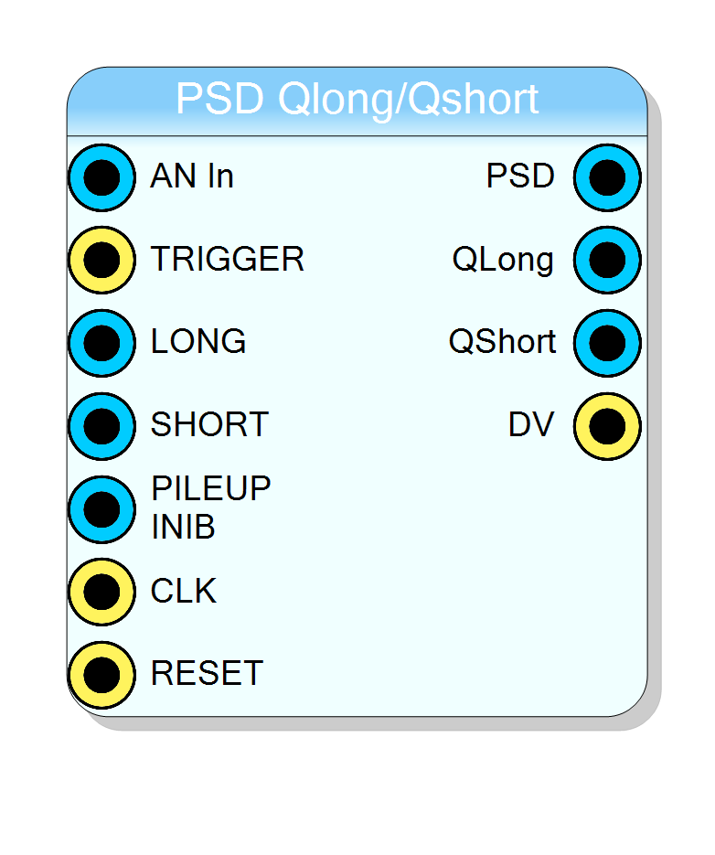
Introduction
Not recommended for new designs. Use QDC/PSD HLS instead for improved functionality including baseline subtraction, configurable PSD formula, pre-trigger integration, and pile-up rejection counters.
The PSD Qlong/Qshort block implements a basic pulse shape discrimination algorithm using the charge integration method.
PSD can be used to distinguish different particle types (e.g., neutrons from gammas) based on their scintillation pulse shape differences.
Pin Description
Usage
PSD Algorithm
The block calculates the PSD value using the following formula:
$$ \text{PSD} = \frac{Q_{\text{short}}}{Q_{\text{long}}} \times 2^{32} $$
where:
- Qlong: Charge integrated over the long time window
- Qshort: Charge integrated over the short time window
The PSD output is a 32-bit fixed-point value. Maximum value (2^32) occurs when Qshort = Qlong.
Limitations
This legacy block has several limitations compared to the newer QDC/PSD HLS block:
| Feature | PSD Legacy | QDC/PSD HLS |
|---|---|---|
| Pre-trigger integration | No | Yes |
| Baseline subtraction | No | Yes |
| PSD formula selection | Fixed (Qshort/Qlong) | Selectable |
| Pile-up rejection counters | No | Yes |
| 16-bit scaled outputs | No | Yes |
| Timestamp capture | No | Yes |
| Gate outputs | No | Yes |
Pre-Trigger Integration Workaround
This block does not implement pre-trigger integration. If pre-trigger capture is required, an external delay must be added to align the trigger with the signal.
Pile-Up Rejection
The block implements basic pile-up rejection by inhibiting measurements if two triggers occur too close together (within the LONG integration window).
Migration to QDC/PSD HLS
For new designs, use the QDC/PSD HLS block which provides:
- Pre-trigger integration (PRE_INT parameter)
- Real-time baseline subtraction
- Selectable PSD formula (Qlong/Qshort or Qshort/Qlong)
- Pile-up rejection with counters (REJ_CNT, DREJ_CNT)
- Both 32-bit and 16-bit charge outputs
- Timestamp capture
- Integration gate outputs for monitoring