
ALU - GATE DIFFERENTIATOR
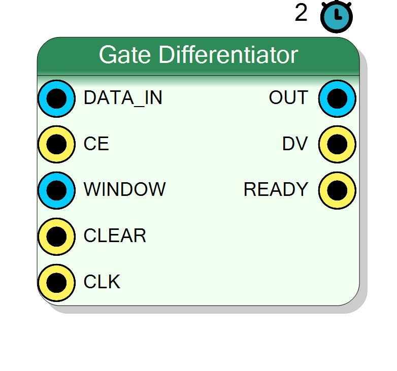
Gated differentiator for pulse shape analysis. Computes the difference between two windowed integrals of the input signal, commonly used for timing extraction and zero-crossing detection in nuclear instrumentation. Features programmable window length and handshake protocol for external synchronization.
Introduction
The Gate Differentiator computes the difference between two consecutive integration windows, producing a derivative-like output:
$$ \mathrm{OUT}[n] = \sum_{i=0}^{W-1} \mathrm{IN}[n+i] - \sum_{i=0}^{W-1} \mathrm{IN}[n-W+i] $$
where W is the window length. This operation is fundamental in Constant
Fraction Discriminators (CFD) and timing trigger circuits for particle
detection systems.
The block provides handshake signals (DV_OUT, READY) for integration
with trigger and data acquisition systems.
Pin Description
DV_OUT is high.
OUT.
Functional description
The differentiator implements a windowed difference operation:
$$ y[n] = \int_{t=n}^{n+W} x[t] , dt - \int_{t=n-W}^{n} x[t] , dt $$
This produces:
- Positive output: When signal is rising
- Zero crossing: At pulse peak (timing reference)
- Negative output: When signal is falling
Applications in timing
In CFD circuits, the zero-crossing of the differentiator output provides
a timing mark independent of pulse amplitude. The WINDOW parameter controls
the derivative time constant:
- Shorter windows: Faster response, more noise sensitivity
- Longer windows: Smoother output, reduced timing jitter
Window length
The WINDOW input sets the integration length for both windows:
- Width: 16 bits (unsigned)
- Default: 16 samples (x"0010")
- Typical range: 4 – 256 samples
Control signals
CE: Clock enable for operationCLEAR: Immediate reset of internal stateREADY: Indicates idle state, ready for new data
Latency
Fixed latency of 2 clock cycles.
Typical use cases
- Zero-crossing detection in CFD circuits
- Timing extraction in nuclear spectroscopy
- Pulse shape discrimination
- Leading-edge timing triggers