
Chronometer (Enable)
Synchronous chronometer that measures elapsed time (in clock cycles) while an enable signal is active. Accumulates time continuously when ENABLE=‘1’, with optional automatic reset on overflow. Configurable counter width from 8 to 64 bits.
Introduction
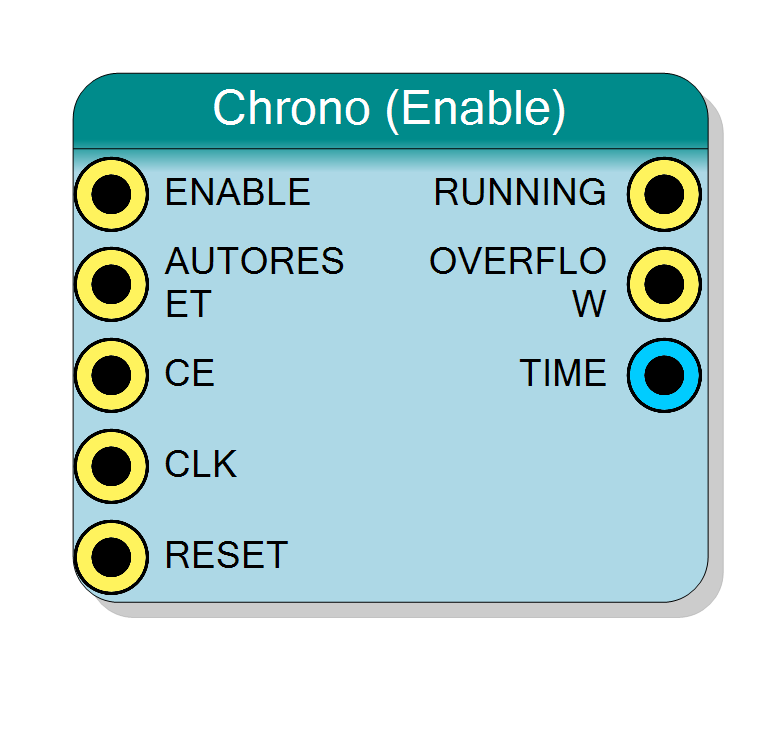
This block measures elapsed time by counting clock cycles while the ENABLE input is high. The chronometer accumulates time continuously and provides three outputs:
- TIME - Current elapsed time count (in clock cycles)
- RUNNING - Indicates when chronometer is actively counting (‘1’ when ENABLE=‘1’)
- OVERFLOW - Pulses high for one cycle when counter wraps around
The counter increments on every rising edge of CLK when both ENABLE=‘1’ and CE=‘1’. When AUTORESET=‘1’, the counter automatically resets to zero after overflow, enabling continuous periodic measurement.
Pin Description
Enable input - controls counting operation.
- ‘1’ = Count enabled (TIME increments each clock)
- ‘0’ = Count paused (TIME holds current value)
This signal can be driven by any logic condition you want to measure.
Automatic reset control (active high).
- ‘1’ = Counter resets to 1 when ENABLE rises from ‘0’ to ‘1’
- ‘0’ = Counter continues from previous value when ENABLE rises
Useful for measuring individual time intervals from the start of each enable pulse.
Clock enable input (active high). Global clock enable for the counter. Typically tied to ‘1’. When CE=‘0’, counting is suspended regardless of ENABLE state.
Default: Connects to ‘1’ if left unconnected.
Clock input. Counter increments on rising edge when ENABLE=‘1’ and CE=‘1’.
Default: Connects to global clock if left unconnected.
Synchronous reset input (active high).
- ‘1’ = Reset counter to 0
- ‘0’ = Normal operation
Default: Connects to global reset if left unconnected.
Running status output.
- ‘1’ = Chronometer is actively counting (ENABLE=‘1’)
- ‘0’ = Chronometer is paused (ENABLE=‘0’)
This is a registered output, delayed by one clock cycle from ENABLE.
Overflow flag output (single-cycle pulse). Pulses high for one clock cycle when counter reaches maximum value (2^N - 1) and wraps to 0.
Use this to detect measurement overflow or as a periodic pulse generator when AUTORESET=‘1’.
Current time count output (unsigned integer). Contains the accumulated clock cycle count. Width is configurable via the Bit Number property.
To convert to real time: Time (seconds) = TIME / CLK_Frequency (Hz)
Properties
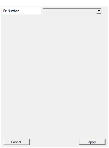
Set the number of bit used in the timer accumulator
Number of bits in the time counter.
Available values: 8, 16, 24, 32, 40, 48, 56, 64
Determines maximum measurable time:
- Max count = 2^BitNumber - 1
- Max time = (2^BitNumber - 1) / CLK_Frequency
Example: 32-bit @ 100 MHz = 42.9 seconds max
Choose the smallest value that meets your requirements to minimize FPGA resource usage.
Default: 32
Options: 8 16 24 32 40 48 56 64
Functional description
The chronometer implements a synchronous up-counter that measures time intervals based on the system clock frequency. The time measurement is controlled by the ENABLE input:
$$ \mathrm{TIME}(n+1) = \begin{cases} \mathrm{TIME}(n) + 1 & \text{if ENABLE=‘1’ and CE=‘1’} \ \mathrm{TIME}(n) & \text{otherwise} \end{cases} $$
Counter behavior
- Counting: Increments by 1 each clock cycle when ENABLE=‘1’ and CE=‘1’
- Paused: Holds current value when ENABLE=‘0’
- Overflow: Occurs when counter reaches maximum value (2^N - 1, where N = Bit Number)
- Auto-reset: If AUTORESET=‘1’, counter resets to 1 when ENABLE rises from ‘0’ to ‘1’
Time calculation
To convert the TIME count to real time:
$$ \text{Elapsed Time (seconds)} = \frac{\mathrm{TIME}}{\text{CLK Frequency (Hz)}} $$
For example, with a 100 MHz clock:
- TIME = 100,000,000 → 1 second elapsed
- TIME = 1,000,000 → 10 milliseconds elapsed
Overflow behavior
With N-bit counter:
- Maximum count: $2^N - 1$
- Overflow period (if running continuously): $\frac{2^N}{\text{CLK Frequency}}$ seconds
Examples:
- 32-bit counter @ 100 MHz: Overflows after ~42.9 seconds
- 64-bit counter @ 100 MHz: Overflows after ~5,849 years
Timing diagram
The diagram shows:
- Counter increments while ENABLE=‘1’
- Counter holds value when ENABLE=‘0’
- Counter resets to 0 when RESET=‘0’ (active low)
- RUNNING output tracks ENABLE input
Typical use cases
- Performance measurement: Measure execution time of FPGA operations
- Timeout detection: Monitor how long a condition persists
- Duty cycle measurement: Measure active time of periodic signals
- Event duration tracking: Record time intervals between events
- Pulse width measurement: Measure width of variable-length pulses
Design considerations
Choosing bit width
Select the counter width based on maximum expected measurement time:
| Bit Width | Max Count | @ 100 MHz | @ 200 MHz |
|---|---|---|---|
| 8 bits | 255 | 2.55 µs | 1.28 µs |
| 16 bits | 65,535 | 655 µs | 328 µs |
| 24 bits | 16,777,215 | 168 ms | 84 ms |
| 32 bits | 4,294,967,295 | 42.9 s | 21.5 s |
| 64 bits | 2^64 - 1 | ~5,849 years | ~2,925 years |
Resource usage
- Each additional bit adds one flip-flop and minor combinational logic
- Wider counters (48-64 bits) have minimal impact on modern FPGAs
- Use smallest width that meets timing requirements to save resources
Using AUTORESET
- AUTORESET=‘0’: Counter continues from previous value, useful for cumulative measurements
- AUTORESET=‘1’: Counter resets to 1 when ENABLE rises, useful for measuring individual pulses
- Monitor OVERFLOW output to detect when counter wraps around