
Between
Checks whether an input value falls within a specified range (between MIN and MAX). Supports both inclusive and exclusive boundary checking with configurable signed/unsigned interpretation.
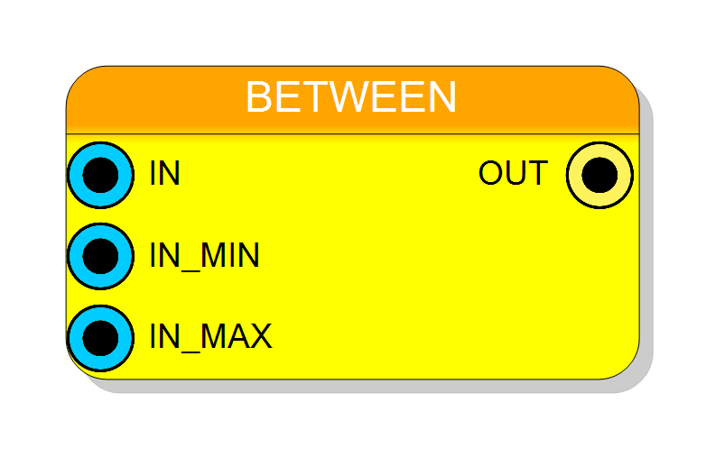
Introduction
This block performs a range check to determine if an input value lies between two boundary values. Two comparison modes are available:
BETWEEN mode (exclusive boundaries): $$ \mathrm{OUT} = \begin{cases} 1 & \text{if } \mathrm{IN_MIN} < \mathrm{IN} < \mathrm{IN_MAX} \ 0 & \text{otherwise} \end{cases} $$
BETWEEN EQUAL mode (inclusive boundaries): $$ \mathrm{OUT} = \begin{cases} 1 & \text{if } \mathrm{IN_MIN} \leq \mathrm{IN} \leq \mathrm{IN_MAX} \ 0 & \text{otherwise} \end{cases} $$
Pin Description
Range check result output.
- ‘1’ when IN is within the range [IN_MIN, IN_MAX]
- ‘0’ otherwise Width: 1 bit
Properties
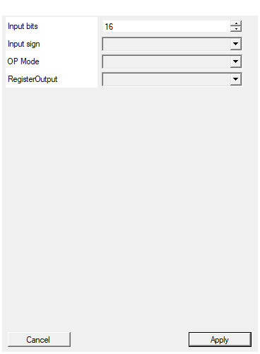
Set the number of bits of the input
Number of bits for all input values (IN, IN_MIN, IN_MAX). Range: 2-2048 bits. All three inputs must have the same width.Default: 16
Range: 2 – 2048
Select the sign/unsign of the input
Selects input interpretation: UNSIGNED (default) or SIGNED (two’s complement) for all inputs.Default: UNSIGNED
Options: UNSIGNED SIGNED
Select between if consider true also in1 = in2
Boundary inclusion: BETWEEN (exclusive, strict inequalities) or BETWEEN EQUAL (inclusive, allows values at boundaries).Default: BETWEEN
Options: BETWEEN BETWEEN EQUAL
Enable one pipeline stage adding a register
Adds an output register stage. Disable (combinational, zero latency) or Enable (registered, 1 clock cycle latency).Default: Disable
Options: Disable Enable
Functional description
The Between comparator performs a dual comparison to check if the input value is within the range defined by IN_MIN and IN_MAX.
Comparison Modes
BETWEEN (exclusive)
Returns ‘1’ only when IN is strictly between the boundaries: $$ \mathrm{OUT} = (\mathrm{IN_MIN} < \mathrm{IN}) \land (\mathrm{IN} < \mathrm{IN_MAX}) $$
BETWEEN EQUAL (inclusive)
Returns ‘1’ when IN is within or at the boundaries: $$ \mathrm{OUT} = (\mathrm{IN_MIN} \leq \mathrm{IN}) \land (\mathrm{IN} \leq \mathrm{IN_MAX}) $$
Implementation
The component implements two comparisons and combines them with an AND operation:
- First: IN > IN_MIN (or IN ≥ IN_MIN for BETWEEN EQUAL)
- Second: IN < IN_MAX (or IN ≤ IN_MAX for BETWEEN EQUAL)
- Result: Both conditions must be true
Example (8-bit unsigned, BETWEEN EQUAL mode)
- IN_MIN = 10, IN_MAX = 20
- IN = 5 → OUT = 0 (below range)
- IN = 10 → OUT = 1 (at lower boundary)
- IN = 15 → OUT = 1 (within range)
- IN = 20 → OUT = 1 (at upper boundary)
- IN = 25 → OUT = 0 (above range)
Latency and Timing
| RegisterOutput | Latency (clock cycles) |
|---|---|
| Disable | 0 |
| Enable | 1 |
Typical use cases
- Range validation for input data
- Threshold detection with upper and lower bounds
- Window comparators for signal processing
- Valid data range checking
- Alarm and limit detection systems