
FLOATING POINT - DIVISION
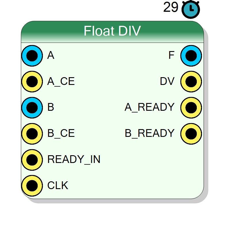
Performs IEEE-754 floating-point division with configurable throughput. Supports both single-precision (32-bit) and double-precision (64-bit) formats. Built on Xilinx Floating-Point IP core with blocking flow control, 29-cycle latency, and adjustable initiation interval (1-26 cycles).
Introduction
The block performs floating-point division of two IEEE-754 encoded values.
On every rising edge of CLK, if both A_CE = 1 and B_CE = 1, the divider computes
$$ \mathrm{F}(n) = \frac{\mathrm{A}(n)}{\mathrm{B}(n)}, $$
where inputs A, B and output F follow IEEE-754 single or double
precision format.
The division is implemented with the Xilinx floating_point IP core configured for Divide operation with blocking flow control, fixed 29-cycle latency, and configurable initiation interval to trade area for throughput.
Pin Description
A_CE = 1 and A_READY = 1.
A_CE = 1, input A is accepted into the pipeline. Can be tied to ‘1’ for continuous operation.
B_CE = 1 and B_READY = 1.
Must not be zero unless division-by-zero behavior is acceptable.
B_CE = 1, input B is accepted into the pipeline. Can be tied to ‘1’ for continuous operation.
DV = 1.
Result = A / B.
F contains a valid quotient.
Asserts 29 clock cycles after corresponding inputs accepted.
A.
May deassert if II > 1 and core is busy.
B.
May deassert if II > 1 and core is busy.
Properties
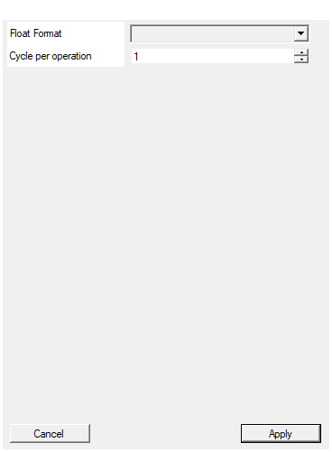
Select between single precision 32 bit and double precision 64 bit
Floating-point precision for all inputs and output:
- Single → 32-bit (8-bit exponent, 24-bit mantissa including implicit bit)
- Double → 64-bit (11-bit exponent, 53-bit mantissa including implicit bit)
All operands must use the same precision.
Default: Single
Options: Single Double
Number of clock cycles to execute a division. Set to 1 to perform division in realtime. Higher number reduce the area usage of the block
Initiation Interval (cycles per operation). Range: 1 - 26.
- 1 → Fully pipelined, maximum throughput, largest area
- 26 → Minimal area, throughput = 1/26 of maximum
Set to 1 for continuous streaming division. Increase to reduce resource usage if throughput is not critical.
Default: 1
Range: 1 – 26
Functional description
The component performs IEEE-754 compliant floating-point division:
$$ F = \frac{A}{B} $$
The operation handles:
- Exponent subtraction with bias correction
- Mantissa division using iterative algorithm
- Result normalization
- Rounding (round-to-nearest, ties-to-even)
Special cases
IEEE-754 special value handling:
x / 1 = x(for finite x)0 / 0 = NaN(invalid operation)x / 0 = ±Inf(division by zero, sign determined by operands)Inf / Inf = NaN(invalid operation)NaN / x = NaN(NaN propagation)
Initiation Interval (II)
The Cycle per operation property sets the initiation interval:
- II = 1 → New operation every cycle (maximum throughput, largest area)
- II = 26 → New operation every 26 cycles (minimum area, reduced throughput)
Higher II values reduce hardware resources (especially DSP and logic) at the cost of lower throughput. For continuous streaming, choose II = 1. For infrequent divisions, larger II saves area.
Timing
The IP has a fixed 29-cycle pipeline latency regardless of II:
| Clock cycle | Event |
|---|---|
| 0 | Inputs A, B presented with A_CE = 1, B_CE = 1 |
| 29 | Output F valid with DV = 1 |
With II = 1, a new operation can start every cycle (fully pipelined). With II > 1, the next operation must wait II cycles before starting.
Typical use cases
- Normalization operations (value / maximum)
- Ratio computation in control systems
- Per-sample gain adjustment
- Inverse calculations when paired with constant numerator