
Serial Bus - Status Packet TX
Transmitter for the 16-byte time/period/PPP/run/frame-number status packet and the paired 2-byte veto packet broadcast over two asynchronous serial lines. All packet fields are driven in parallel and an external strobe triggers each broadcast.
Introduction
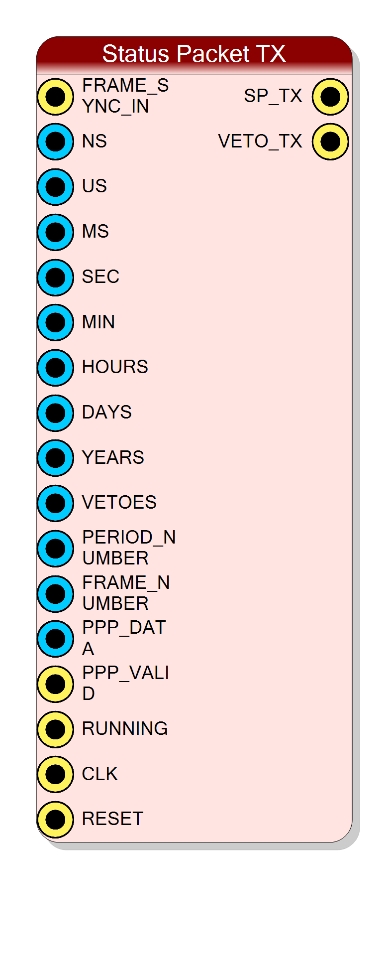
The Status Packet TX block builds a fixed-format timing broadcast from a set of parallel input buses and drives it on two unidirectional UART-like lines:
- SP_TX - status packet line (timestamp + period + PPP + running + frame number)
- VETO_TX - companion veto line (2-byte veto word per veto change)
Both lines share the same baud rate and are intended to feed a matching Status Packet RX component on the receiving side.
Key features:
- Parallel inputs for every packet field (no AXI register file required)
- External rising-edge FRAME_SYNC_IN triggers each broadcast
- Optional CRC32 trailer (4 extra bytes) for receiver-side verification
- Veto line automatically retransmits whenever the veto bitmap changes
- Internal UART divider computed from the configured clock and baud rate
Pin Description
PPP_VALID is high; the last sampled value
is sent in byte 10 of every packet.
PPP_DATA.
When HIGH, PPP_DATA is captured into the internal latch.
CLK_FREQ_HZ / BaudRate ratio of 16 or more is recommended).
Default: Acquisition clock.
Properties
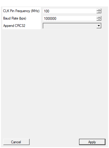
Set the input clock frequency in MHz (used to compute the UART divider together with the Baud Rate)
Frequency of the CLK input in MHz. Combined with the baud rate to compute the internal UART divider.
Typical values:
- 50 MHz: V2495 default
- 80 MHz: DT5550 default
- 100-200 MHz: High-speed designs
Default: 100
Range: 1 – 500
Set the status packet serial baud rate in bits per second (used to compute the UART divider)
Status packet line speed in bits per second. Both SP_TX and VETO_TX run at this rate.
Common values used with this protocol:
- 9600: legacy / long cable runs
- 115200 - 921600: typical lab setups
- 1000000: default high-speed setting
The synthesized UART divider is computed as
floor(CLK_FREQ_HZ / BaudRate). Pick the same rate as on the
receiving side; mismatches of more than a few percent may corrupt the
transferred bytes.
Default: 1000000
Range: 300 – 10000000
When enabled, the transmitter appends 4 CRC32 bytes after each status packet
Appends a CRC32 trailer (4 extra bytes) at the end of every status packet. Useful in conjunction with a Status Packet RX component configured with CRC verification.
- Disabled: 16 payload bytes per packet, no CRC.
- Enabled: 16 payload bytes + 4 CRC32 bytes (Ethernet polynomial
0xEDB88320, LSB first).
The setting must match the receiver configuration; otherwise the receiver may either flag a stuck packet or miss the CRC field entirely.
Default: Disabled
Options: Disabled Enabled
Functional description
The block is driven by an external active-high FRAME_SYNC_IN pulse. On each rising edge of that pulse the current state of the time/period/PPP/ run/frame-number inputs is latched and serialized on SP_TX preceded by a long start-low frame-sync marker. The veto transmitter on VETO_TX runs in parallel and broadcasts a 2-byte word every time the VETOES[15:0] input changes value between two frame syncs.
Both serial lines use 8-N-1 framing (8 data bits, no parity, 1 stop bit) at the configured baud rate. Idle level is HIGH.
Status packet layout (SP_TX line)
After the frame-sync marker, 16 payload bytes are sent in this order (an additional 4 CRC32 bytes are appended if the CRC trailer is enabled):
| Byte | Source field |
|---|---|
| 0 | { '0' & YEARS[6:0] } |
| 1 | DAYS[8:1] |
| 2 | { DAYS[0] & HOURS[4:0] & MIN[5:4] } |
| 3 | { MIN[3:0] & SEC[5:2] } |
| 4 | { SEC[1:0] & MS[9:4] } |
| 5 | { MS[3:0] & US[9:6] } |
| 6 | { US[5:0] & NS[9:8] } |
| 7 | NS[7:0] |
| 8 | PERIOD_NUMBER[15:8] |
| 9 | PERIOD_NUMBER[7:0] |
| 10 | PPP_DATA[7:0] (latched when PPP_VALID = 1) |
| 11 | { "0000000" & RUNNING } |
| 12 | FRAME_NUMBER[31:24] |
| 13 | FRAME_NUMBER[23:16] |
| 14 | FRAME_NUMBER[15:8] |
| 15 | FRAME_NUMBER[7:0] |
| 16 | CRC32[7:0] (LSB, only if CRC trailer enabled) |
| 17 | CRC32[15:8] (only if CRC trailer enabled) |
| 18 | CRC32[23:16] (only if CRC trailer enabled) |
| 19 | CRC32[31:24] (MSB, only if CRC trailer enabled) |
The CRC32 is computed with the Ethernet polynomial 0xEDB88320 over the
16 payload bytes only.
Veto packet layout (VETO_TX line)
Between two frame syncs, the veto transmitter maintains an OR-accumulated copy of the VETOES input. Each time the accumulated value changes, it emits one veto pulse followed by 2 bytes:
| Byte | Field |
|---|---|
| 0 | VETOES[15:8] |
| 1 | VETOES[7:0] |
The accumulator is cleared automatically at the next frame sync, so a vetoed channel is reported again when the next frame begins.
PPP latching
PPP_DATA is latched internally whenever PPP_VALID goes high; the
latched value is transmitted in byte 10 of the next packet. If no
PPP_VALID pulse arrived in the meantime, the last latched value is
re-sent. After reset the latched value is 0x00.
UART clock divider
The internal divider that converts the system clock into the UART baud reference is computed at synthesis time as:
$$ DIV = \left\lfloor \frac{f_{CLK}}{BaudRate} \right\rfloor $$
For example, 100 MHz / 1 Mbps → DIV = 100, 50 MHz / 9600 bps → DIV = 5208.
Pick the same baud rate on transmitter and receiver; mismatches of more than a few percent will produce byte-level errors at the far end.
Triggering the broadcast
FRAME_SYNC_IN is active high and edge-triggered:
- While
FRAME_SYNC_INis HIGH, the baud clock generator is held in reset so no UART activity happens. This is the moment the transmitter snapshots the parallel inputs. - On the falling edge, the baud clock starts and the long start-low frame-sync marker is emitted on SP_TX, followed by the 16 (or 20) bytes.
Make sure the parallel inputs are stable while FRAME_SYNC_IN is high.
Reset Behavior
The RESET input is active high (driven from the project Global Reset by default):
- Both UART state machines return to idle.
- SP_TX and VETO_TX are forced HIGH (idle).
- The internal veto accumulator and PPP latch are cleared.