
ADD [TM]
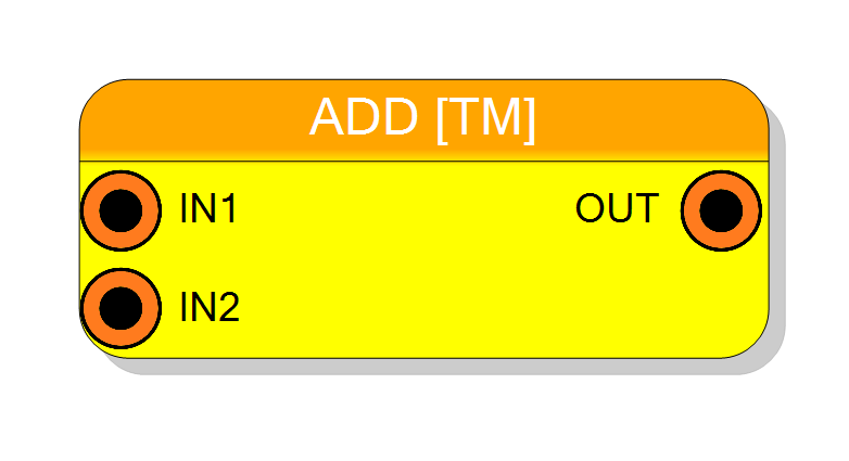
Time-multiplexed two-input adder with configurable overflow protection. Adds two TM data streams (or one TM + one scalar) with optional output register stage. Supports signed/unsigned arithmetic up to 256 bits with saturating overflow logic. Pipeline latency: 0 or 1 cycle (configurable).
Introduction
This block performs sample-by-sample addition of two input streams in time-multiplexed (TM) mode, producing a summed output stream.
On every clock cycle, the component computes:
$$ \mathrm{OUT}(n) = \mathrm{IN1}(n) + \mathrm{IN2}(n), $$
where IN1 is always TM, and IN2 can be either TM (same factor as IN1) or scalar (replicated across all TM phases). Optional overflow saturation ensures output values do not wrap around on overflow.
Pin Description
Input bits × TM Factor 1
Arithmetic type set by Input sign property.
Second input data stream, TM or scalar.
- If TM Factor 2 = ENABLED: TM bus of width
Input bits × TM Factor 1 - If TM Factor 2 = DISABLED: Scalar of width
Input bits
Arithmetic type matches IN1.
Sum output, always TM (same factor as IN1).
Width: Output bits × TM Factor 1
- Output bits = Input bits (SAME INPUT)
- Output bits = Input bits + 1 (EXTRA BIT)
Valid immediately (latency = 0) or after 1 cycle if registered.
Properties
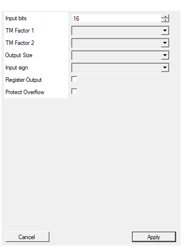
Set the number of bits of the input
Number of bits per input sample ($N_\text{in}$). Range: 2 – 256. Applies to both IN1 and IN2.Default: 16
Range: 2 – 256
Select the Time Multiplexing factor for input 1
Time-multiplexing factor for IN1 (and OUT). Allowed values: 1, 2, 4, 8, 16, 32. Determines how many parallel additions are performed per clock.Default: 4
Options: 1 2 4 8 16 32
Select the Time Multiplexing factor for input 2
Time-multiplexing mode for IN2:
ENABLED→ IN2 is TM with same factor as IN1 (element-wise addition)DISABLED→ IN2 is scalar, replicated to all TM phases
Default: ENABLED
Options: DISABLED ENABLED
Select if the output should have one extra bit to avoid overflow in the result
Output bit width configuration:
SAME INPUT→ Output width = Input width (wrap-around on overflow)EXTRA BIT→ Output width = Input width + 1 (prevents overflow)
Default: SAME INPUT
Options: SAME INPUT EXTRA BIT
Select the sign/unsign of the input
Arithmetic type of inputs and output:
UNSIGNED→ Non-negative integers, wrap-around at $2^{N}-1$SIGNED→ Two’s complement, range $[-2^{N-1}, 2^{N-1}-1]$
Default: UNSIGNED
Options: UNSIGNED SIGNED
Enable one pipeline stage adding a register. Improve system timing but increase pipeline delay from 0 to 1 clock cycle
Enable output pipeline register:
false→ Combinational output (latency = 0, may limit max clock frequency)true→ Registered output (latency = 1 cycle, improves timing)
Default: False
Enable overflow protection logic. The overflow logic will saturate output to maximum value in overflow condition. This option, if enabled, negatively impact on system timing.
Enable overflow saturation logic:
false→ Arithmetic overflow wraps around (modulo 2^N)true→ Saturates to maximum representable value on overflow
Warning: Enabling this adds combinational logic that may degrade timing. Consider using EXTRA BIT mode instead for overflow-free operation.
Default: False
Functional description
The component implements pure combinational or registered addition in VHDL, replicated N times (where N = TM Factor 1) to support time-multiplexed data streams.
Input modes
- IN1: TM bus of width
Input bits × TM Factor 1(always TM) - IN2: Can be configured as:
- ENABLED (TM Factor 2): TM bus of same width as IN1, element-wise addition
- DISABLED (TM Factor 2): Scalar input of width
Input bits, added to all IN1 phases
Output configuration
- SAME INPUT: Output bit width = Input bits (wrap-around on overflow)
- EXTRA BIT: Output bit width = Input bits + 1 (prevents overflow by extending range)
Optional features
- Register Output: Adds one pipeline stage (latency = 1), improves timing closure
- Protect Overflow: Saturates output to max value on overflow (impacts timing)
Mathematical background
For N-bit signed addition:
$$ y = x_1 + x_2 $$
Overflow occurs when:
- Signed: $|x_1 + x_2| > 2^{N-1} - 1$
- Unsigned: $x_1 + x_2 > 2^N - 1$
With EXTRA BIT enabled, output width becomes N+1, doubling the representable range.
With Protect Overflow enabled, hardware saturates:
$$ y_\text{sat} = \begin{cases} 2^{N-1} - 1 & \text{if } y > 2^{N-1} - 1 \text{ (positive overflow)} \ -2^{N-1} & \text{if } y < -2^{N-1} \text{ (negative overflow)} \ y & \text{otherwise} \end{cases} $$
Timing
Pipeline latency depends on Register Output setting:
| Register Output | Latency (clock cycles) |
|---|---|
| Disabled | 0 |
| Enabled | 1 |
Typical use cases
- Summing multi-channel detector signals
- Combining trigger logic outputs
- Accumulation stages in digital filters
- Baseline restoration (TM data + scalar offset)
Waveform example
Example with TM Factor 1 = 4, IN1 = [10, 20, 30, 40], IN2 = [1, 2, 3, 4], Register Output = Enabled.
Note: 1 clock cycle latency when register is enabled.