
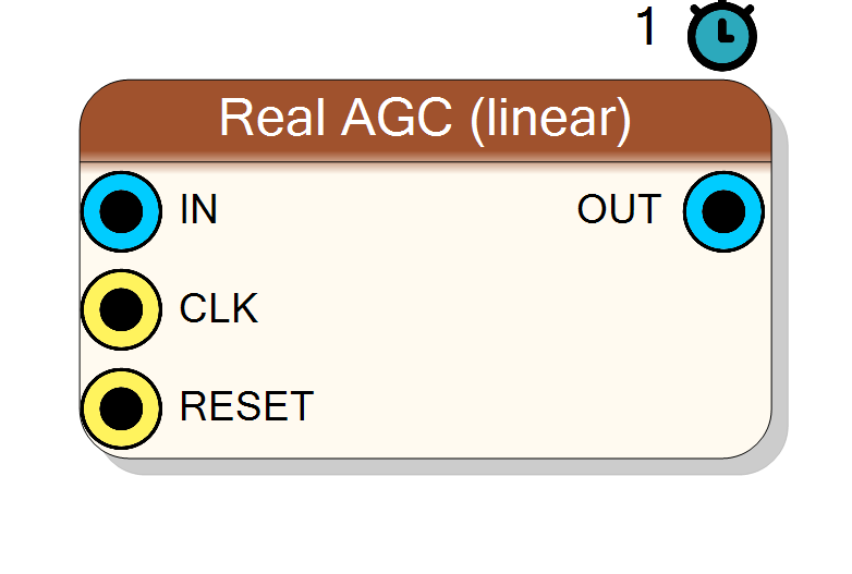
RF Real AGC (linear)
Single-channel (real) Automatic Gain Control: a closed-loop, linear power-normalising amplifier that continuously adjusts an internal gain so that the mean-square of the output tracks a programmable target power. Same loop topology as the complex AGC with half the multipliers and registers. Typical use: level a real audio / IF stream to a constant amplitude ahead of a demodulator, detector, or fixed-threshold stage.
Introduction
The Real AGC (linear) block multiplies the input by an adaptive gain and drives a control loop that pushes the output power toward a fixed target. The full per-sample loop is:
y = clamp( (x * gain) >> GAIN_FRAC , OUT_MIN , OUT_MAX )
avg += (y*y - avg) >> AVG_SHIFT (leaky power estimate)
err = TARGET - avg
gain += err >> LOOP_SHIFT (integrator / loop filter)
gain = clamp(gain, MIN_GAIN, MAX_GAIN)
It is a linear AGC: the gain is applied as a plain multiply and the
error is driven from the mean-square (y*y) power estimate rather than a
log/dB detector. gain is an unsigned fixed-point number with GainFrac
fractional bits, so gain = 2^GainFrac corresponds to unity gain.
IN ──▶(×)──▶[ clamp ]──▶ OUT
▲ │
gain ◀─[ loop ]◀─[ y*y avg ]◀─┘
When the output power sits below the target, err is positive and the
integrator ramps the gain up; when it exceeds the target the gain ramps
down. The steady state is reached when avg ≈ TARGET.
Pin Description
InputSize) bits.
gain to unity
(2^GainFrac) and avg to 0. Default: Global reset.
clamp((x*gain) >> GainFrac). Signed, Output Bit Width (OutputSize) bits,
saturated to the output range.
Properties
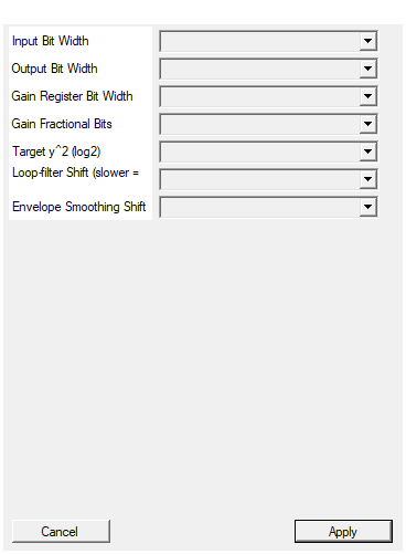
Bit width of the input sample (signed).
Bit width of the signed input sample. Range 4 to 32, default 16. Changing this triggers a redesign.Default: 16
Options: 4 5 6 7 8 9 10 11 12 13 14 15 16 17 18 19 20 21 22 23 24 25 26 27 28 29 30 31 32
Bit width of the output sample (signed). Typical: InputSize + 2.
Bit width of the signed output sample. Range 8 to 40, default 18. Output is saturated to this width. Typical value:InputSize + 2 for boost headroom. Changing this triggers a redesign.
Default: 18
Options: 8 9 10 11 12 13 14 15 16 17 18 19 20 21 22 23 24 25 26 27 28 29 30 31 32 33 34 35 36 37 38 39 40
Bit width of the internal gain (unsigned).
Bit width of the internal unsigned gain register. Range 12 to 24, default 18. Together withGainFrac it sets the maximum gain
(≈ 2^(GainSize - GainFrac)). Changing this triggers a redesign.
Default: 18
Options: 12 13 14 15 16 17 18 19 20 21 22 23 24
Fractional bits of the gain (gain=2^GainFrac means unity).
Number of fractional bits of the gain.gain = 2^GainFrac is unity
gain. Range 4 to 20, default 12. Also sets the minimum gain
floor 2^(GainFrac-4) (= 1/16). Changing this triggers a redesign.
Default: 12
Options: 4 5 6 7 8 9 10 11 12 13 14 15 16 17 18 19 20
Target power = 2^TargetLog2. For sinusoids set 1 bit lower than the complex AGC for the same audible level.
Target output power as a power of two:mean(y^2) = 2^TargetLog2.
Range 8 to 40, default 25. For a sinusoid, set this one bit
lower than the complex AGC to obtain the same amplitude
(mean(y^2) = A^2/2 for a real tone). Does not force a redesign.
Default: 25
Options: 8 9 10 11 12 13 14 15 16 17 18 19 20 21 22 23 24 25 26 27 28 29 30 31 32 33 34 35 36 37 38 39 40
Integrator shift; larger = slower AGC. 12-20 typical.
Integrator (loop-filter) shift:gain += err >> LoopShift. Larger =
slower, smoother AGC; smaller = faster tracking. Range 4 to 24,
default 16 (12–20 typical). Does not force a redesign.
Default: 16
Options: 4 5 6 7 8 9 10 11 12 13 14 15 16 17 18 19 20 21 22 23 24
Leaky IIR shift for the y^2 estimate. 4-10 typical.
Leaky-IIR shift for they^2 power estimate: avg += (y*y - avg) >> AvgShift. Larger averages over more samples (steadier gain, slower
envelope response). Range 0 to 16, default 6 (4–10 typical).
Does not force a redesign.
Default: 6
Options: 0 1 2 3 4 5 6 7 8 9 10 11 12 13 14 15 16
Usage
Control-loop model
Three state elements form the loop:
- avg — a leaky-integrator (first-order IIR) estimate of the output
power
E[y^2], updated asavg += (y*y - avg) >> AvgShift. This is a one-pole low-pass with time constant~2^AvgShiftsamples; it smooths the instantaneousy*yso the loop reacts to envelope power rather than sample-by-sample ripple. - err = TARGET - avg — the power error, where
TARGET = 2^TargetLog2. - gain — an integrator updated by
gain += err >> LoopShift. A largerLoopShiftmakes each correction smaller, i.e. a slower, smoother AGC; a smaller value tracks faster but with more gain ripple / possible pumping.
Because the error feeds an integrator, the loop has zero steady-state
power error (within quantisation): at lock avg ≈ 2^TargetLog2.
Target power note (real vs complex)
For a pure sinusoid of amplitude A, the real signal has
mean(y^2) = A^2 / 2, whereas a complex tone A*(cos + j*sin) has
|.|^2 = A^2 at every sample. The two AGCs therefore lock a sinusoid to
different amplitudes for the same TargetLog2. To get the same output
level from this real AGC as from the complex AGC, set TargetLog2 one
bit lower here.
Fixed-point datapath and bit widths
All signal data is signed two’s complement; the gain is unsigned.
IN: signedInputSizebits.OUT: signedOutputSizebits, clamped (saturated) to[-2^(OutputSize-1), 2^(OutputSize-1) - 1]. TypicalOutputSize = InputSize + 2to give the AGC headroom to boost small inputs without immediate clipping.gain: unsignedGainSizebits,GainFracfractional bits. Unity =2^GainFrac.- Product
x * gain:InputSize + GainSizebits, arithmetic-shifted right byGainFracto align back to sample scale. - Power estimate
avgandy*y: signed2*OutputSize + 8bits — wide enough to hold the squared full-scale output plus 8 guard bits for the leaky-integrator accumulation. - Gain update is computed in
GainSize + 4bits to avoid overflow during the clamp.
Gain limits (clamp)
The gain integrator is bounded to keep the loop stable and prevent runaway on silence:
MIN_GAIN = 2^(GainFrac - 4) -> linear min = 1/16 (-24 dB)
MAX_GAIN = 2^GainSize - 1 -> linear max ≈ 2^(GainSize - GainFrac)
With the defaults (GainSize = 18, GainFrac = 12) the gain ranges from
1/16 up to ≈ 2^6 = 64 (about +36 dB). Widen GainSize to allow more
boost of very weak signals.
Feedback / state registers and reset
RESET is the HLS synchronous reset (ap_rst). On reset the loop state is
initialised to a safe starting point:
gain=2^GainFrac(unity gain), so the very first output equals the input (scaled toOUT) before the loop adapts.avg= 0, so the loop initially sees maximum positive error and begins ramping the gain toward the target at the rate set byLoopShift.
After release the AGC converges to the target power over roughly
2^LoopShift (loop) combined with 2^AvgShift (envelope smoothing)
samples; the dominant term is normally LoopShift.
Latency and throughput
#pragma HLS PIPELINE II=1: one sample per clock.- 1-clock latency (registered output).
- All data ports use the
ap_noneinterface — no ready/valid handshake. Every tuning value (TargetLog2,LoopShift,AvgShift, gain format) is baked in at synthesis time; no top-level control pins are created.
Tuning guidance
- TargetLog2 — sets the output level:
mean(y^2) = 2^TargetLog2, i.e. RMS ≈2^(TargetLog2/2). Keep RMS comfortably below2^(OutputSize-1)to leave crest-factor headroom before the output clamp engages. - LoopShift (12–20 typical) — attack/decay speed. Larger = slower and smoother, less pumping; smaller = faster tracking of level changes.
- AvgShift (4–10 typical) — envelope smoothing. Larger averages the power over more samples (steadier gain, slower response to bursts).
Typical applications
- Constant-level audio / IF ahead of an FM/AM demodulator or a fixed-threshold detector.
- Fading compensation on a real IF channel (slow LoopShift).
- Normalising a variable-amplitude stream so a downstream fixed-point stage sees a predictable dynamic range.
- Squelch-friendly leveling — the
MIN_GAINfloor stops the loop from amplifying noise to full scale during silence.
Resources & Timing
-
Latency: 1 clock cycle
-
Throughput: 1 sample per clock (II=1)
Implemented with Vitis HLS. Single-multiplier signal path (x * gain)
plus one squarer (y*y) for the power estimate — roughly two DSP48
slices, half the arithmetic of the complex AGC. Three state registers:
gain, avg, and the pipelined output. No BRAM. On ap_rst, gain
resets to unity (2^GainFrac) and avg to 0. The output clamp
(saturation) and the gain-integrator clamp (MIN_GAIN..MAX_GAIN) keep
the loop bounded and stable.