
RF Goertzel Sliding (per-sample)
Sliding-DFT single-bin tone monitor. The ‘moving-average’ companion of the block Goertzel: it maintains one DFT bin X(k) over a SLIDING window of N samples and outputs |X(k)|^2 on EVERY input sample, instead of once per N-sample block. Typical use: continuous narrowband power / envelope tracking of one tone with no block latency.
Introduction
The Goertzel Sliding (per-sample) block tracks a single DFT bin X(k)
continuously: it emits an updated power |X(k)|^2 on every input
sample over a sliding window of the last N samples, rather than one
value per non-overlapping block. It is the sliding-DFT (SDFT) counterpart
of Component_Goertzel.
Instead of the block Goertzel recurrence, it uses the sliding-DFT update
(W = e^{j*2*pi*k/N} = cos(w) + j*sin(w)):
X[n] = r * W * ( X[n-1] + x[n] - x[n-N] )
A length-N delay line holds the sample x[n-N] leaving the window, so
each new sample slides the window forward by one and updates the bin with
a single complex twiddle multiply. The power is |X[n]|^2 = Xr^2 + Xi^2.
The optional damping factor r = 1 - 2^-DampShift bleeds off the
marginal-stability error that a pure SDFT (r = 1) accumulates over long
runs; DampShift = 0 is exact but can drift, 12..16 is a safe default.
Selectivity and resolution are identical to the block Goertzel: the bin is
snapped to k = round(N*f/Fs), giving a ~Fs/N-wide main lobe and a
resolution of Fs/N. The difference is purely the per-sample output
and the N-deep delay line it costs.
For a once-per-block output use Component_Goertzel; to monitor several tones with one shared multiplier use Component_GoertzelMulti.
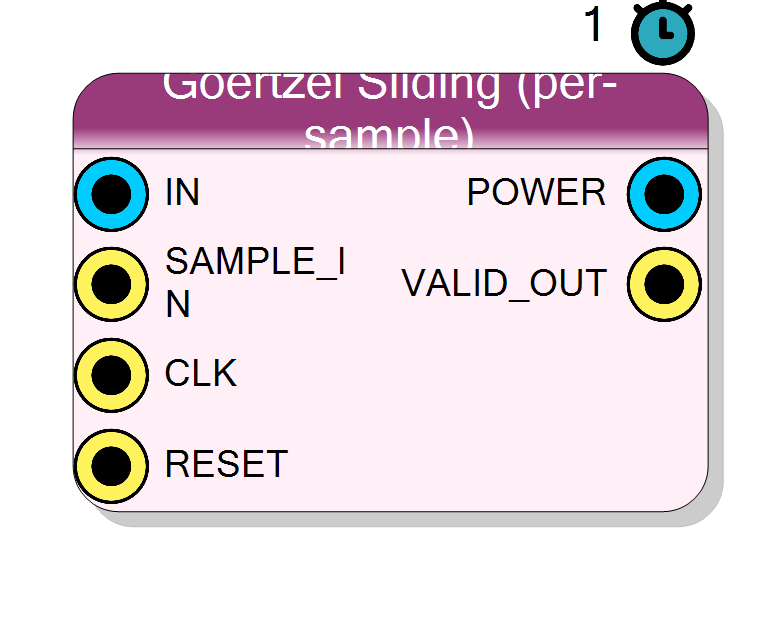
Pin Description
|X(k)|^2, updated on every SAMPLE_IN. The
first N-1 values after reset are the fill-up transient. Signed bus,
2(InputSize + ceil(log2 N) + 2) + 4* bits; the value is
non-negative.
Properties
Real: one input channel. Complex: I/Q input.
Real: single input channelIN (one history line). Complex:
I/Q input IN_I / IN_Q (two history lines, true one-sided bin).
Default Real.
Default: Real
Options: Real Complex
Bit width of the input sample(s).
Bit width of each signed input sample. Range 4..32, default 16.Default: 16
Options: 4 5 6 7 8 9 10 11 12 13 14 15 16 17 18 19 20 21 22 23 24 25 26 27 28 29 30 31 32
Bit width of the cos/sin coefficients.
Bit width of the signedcos/sin twiddle coefficients (scale
2^(CoefSize-2)). One of 12, 14, 16, 18, 20, 24. Default 18.
Default: 18
Options: 12 14 16 18 20 24
Sliding window / DFT size: resolution Fs/N.
Sliding window / DFT size N. ResolutionFs/N; also the depth of the
history delay line (BRAM cost scales with N). One of
16, 32, 64, 128, 256, 512, 1024, 2048, 4096, 8192. Default 256.
Default: 256
Options: 16 32 64 128 256 512 1024 2048 4096 8192
Sample rate of the data feeding this block.
Sample rate (Hz) of the data feeding this block. Used to map the target frequency to a DFT bink = round(N*f/Fs). Default
1000000.
Default: 1000000
Tone to monitor (nearest DFT bin).
Target tone to monitor (Hz). Snapped to the nearest DFT bink = round(N*f/Fs); the actual monitored frequency is k*Fs/N.
Default 50000. Normally set from the Goertzel Designer.
Default: 50000
SDFT stability: r = 1 - 2^-shift. 0 = exact but drifts over long runs; 12-16 = safe.
SDFT stability control:r = 1 - 2^-shift. 0 = exact SDFT but the
marginally-stable resonator can drift over long runs; 10..18 pull
the pole slightly inside the unit circle so rounding error decays.
One of 0, 10, 12, 14, 16, 18. Default 14.
Default: 14
Options: 0 10 12 14 16 18
Config produced by the Goertzel Designer.
Hidden JSON blob produced by the Goertzel Designer (tone + hardware config). Managed by the visual designer, not edited by hand.Usage
Sliding DFT (SDFT)
A block Goertzel gives one bin value per N samples. The sliding DFT keeps
the same bin X(k) up to date on every sample by recognising that sliding
the length-N window forward by one sample changes the bin by removing the
oldest sample and adding the newest, then rotating by the bin twiddle:
X[n] = r * W * ( X[n-1] + x[n] - x[n-N] )
W = cos(w) + j*sin(w), w = 2*pi*k/N
power = Xr^2 + Xi^2
Implementation per sample:
- push
x[n]into anN-deep history and read outx[n-N]; - form
s = damp(X[n-1]) + (x[n] - x[n-N]); - rotate:
Xr = cos(w)*sr - sin(w)*si,Xi = sin(w)*sr + cos(w)*si(one complex twiddle multiply); - output
Xr^2 + Xi^2.
The first N-1 outputs after reset are the window filling up (a
transient); the bin is only fully valid once the delay line holds a full
window.
Damping and SDFT stability
A pure SDFT resonator sits exactly on the unit circle (marginally stable),
so fixed-point rounding error can accumulate without bound over long runs.
Multiplying the recursion by r = 1 - 2^-DampShift pulls the pole
slightly inside the unit circle so old error decays:
DampShift = 0 -> r = 1 exact, but drifts over long runs
DampShift = 12..16 -> r ~ 1 tiny bias, bounded error (safe)
Larger DampShift means r closer to 1 (less bias, weaker leakage
control); smaller means stronger damping. Default 14.
Real vs complex input
- Real (
SignalType = Real): one inputIN, one real history line;siis driven only by the fed-back imaginary state. - Complex (
SignalType = Complex):IN_I/IN_Qwith two history lines (hist_i,hist_q); bothsrandsitake an input difference, giving a true one-sided complex bin.
In both cases the twiddle multiply and |X|^2 are the same.
DFT-bin snapping and resolution
k = round(N * f / Fs) (0 <= k < N)
f_k = k * Fs / N (actual monitored frequency)
df = Fs / N (resolution / bin spacing, ~main-lobe width)
Identical selectivity to the block Goertzel; only the update cadence differs.
Coefficients
COS0 = cos(w), SIN0 = sin(w) are quantised by the plugin to signed
CoefSize bits (scale 2^(CoefSize-2)) and applied in the twiddle
multiply (result shifted right by COEF_SHIFT = CoefSize-2).
Bit widths
Data is signed two’s complement.
IN/IN_I/IN_Q: signedInputSizebits.STATE_SIZE = InputSize + ceil(log2 N) + 2.POWER:POW_SIZE = 2*STATE_SIZE + 4bits (non-negative value).
Timing and handshake
#pragma HLS PIPELINE II=1,ap_ctrl_none: free-running, one call per system clock.SAMPLE_INpulses once per new input sample; the SDFT updates only on those pulses.VALID_OUTmirrorsSAMPLE_IN(high whenever a sample is processed): a freshPOWERis produced every sample. Note the firstN-1results after reset are the fill-up transient.- Latency reported to the diagram is 1 clock.
Reset
RESET (ap_rst) clears the delay line(s), the running bin state
Xr/Xi, the write index and the last power. After reset the window must
refill (N-1 samples) before the output is fully meaningful.
Visual designer
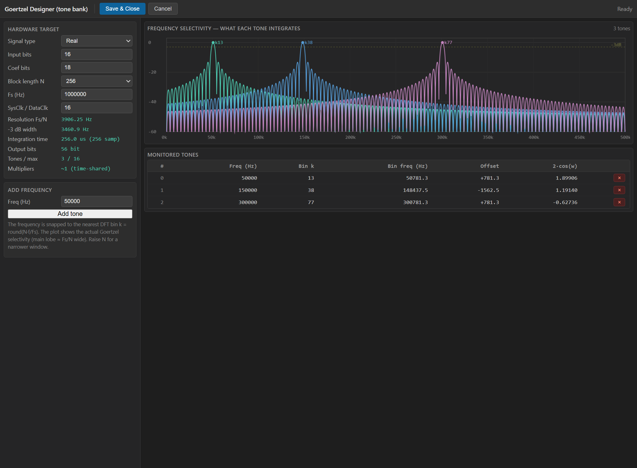
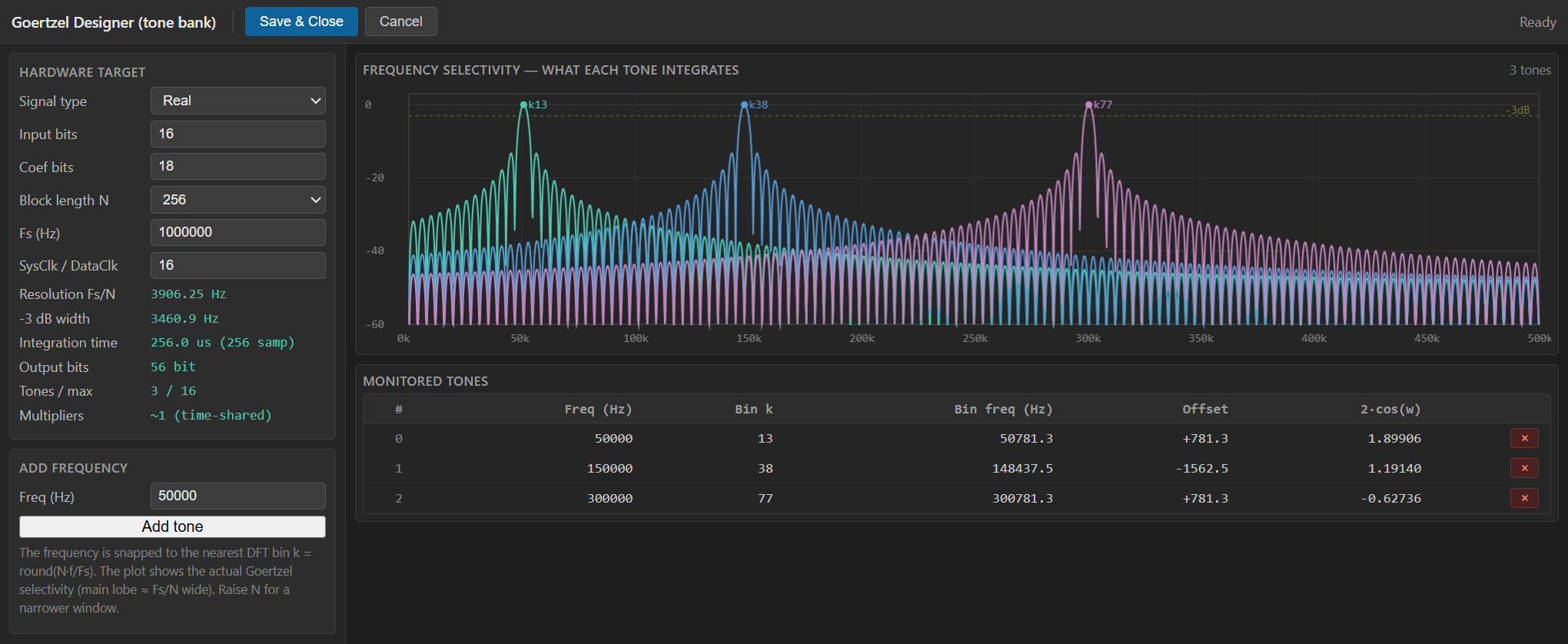
This block is configured through the Goertzel Designer (a WebView2
graphical tool), not the property grid. Double-click the block to open
it. In sliding mode you set the hardware target (signal type, input/
coefficient bits, window length N, Fs and the Damping shift) and enter
the target frequency to monitor; the tool snaps it to the nearest DFT
bin k = round(N*f/Fs), draws the frequency-selectivity plot (the
Goertzel/SDFT main lobe, ~Fs/N wide, showing what the bin integrates)
and shows a live resource / result estimate: resolution Fs/N, -3 dB
width, integration time, output bits and multiplier count. Save & Close
writes the configuration and quantised coefficients back into the block.
Typical applications
- Continuous narrowband power / envelope tracking of one tone with no block latency (a new reading every sample).
- Fast tone presence / onset detection where waiting N samples for a block result is too slow.
- Low-latency line tracking feeding a threshold or AGC.
Resources & Timing
-
Latency: 1 clock per sample; a fresh POWER every sample (window fill-up transient = N-1 samples)
-
Throughput: 1 input sample per SAMPLE_IN pulse (II=1, free-running ap_ctrl_none)
Implemented with Vitis HLS. Per sample: one N-deep history line (two in
complex mode) plus one complex twiddle multiply (~4 real multiplies) and
the |X|^2 squaring. The N-deep history is the main extra cost over the
block Goertzel and is typically mapped to BRAM, growing with N. Optional
damping (r = 1 - 2^-DampShift) is a cheap subtract-shift that keeps the
fixed-point SDFT bounded. Choose this variant when you need a power
reading on every sample (low latency); use the block Goertzel when a
once-per-N result is enough and you want to save the delay-line BRAM.