
RF Real DC Blocker (IIR HP)
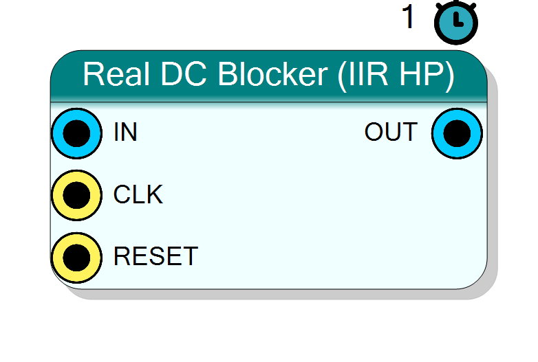
Single-channel (real) DC blocker: a first-order IIR high-pass filter that removes the DC offset / very-low-frequency drift from a real sample stream while passing everything above a tunable corner set by the Alpha coefficient. Half the state and half the arithmetic of the complex DC blocker. Typical use: strip the DC bias from an ADC channel or the residual DC term left after a real mixdown.
Introduction
The Real DC Blocker (IIR HP) implements the classic single-pole / single-zero DC-blocking high-pass filter on a single real channel:
y[n] = x[n] - x[n-1] + alpha * y[n-1]
The zero at z = 1 (the x[n] - x[n-1] term) forces the DC gain to
exactly zero, and the pole at z = alpha (just inside the unit circle)
keeps the passband flat down to a very low corner frequency. The closer
alpha is to 1, the lower the high-pass corner and the slower the block
tracks a changing DC level.
Everything is fixed-point. alpha is quantised to a 15-bit fractional
constant baked into the netlist at synthesis time:
alpha_num = round(alpha * 2^15) (ALPHA_SHIFT = 15)
alpha = alpha_num / 32768
so the feedback term is evaluated as (alpha_num * y[n-1]) >> 15. For the
default alpha = 0.99 this gives alpha_num = 32440.
IN ──▶[ z^-1 zero ]──▶(+)──▶ OUT
▲
alpha · z^-1 (pole)
Pin Description
InputSize) bits.
x_prev and y_prev
feedback registers to zero. Default: Global reset.
x[n] - x[n-1] + alpha*y[n-1]. Signed,
InputSize + 1 bits.
Properties
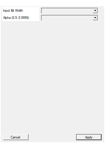
Bit width of the input sample (signed). Output = InputSize+1.
Bit width of the signed input sample. Range 4 to 32, default 16. The output width is fixed atInputSize + 1.
Default: 16
Options: 4 5 6 7 8 9 10 11 12 13 14 15 16 17 18 19 20 21 22 23 24 25 26 27 28 29 30 31 32
IIR feedback coefficient. Closer to 1 = lower HP cutoff = slower DC tracking.
IIR feedback coefficient (the pole locationz = alpha). Closer to 1
means a lower high-pass corner and slower DC tracking. Selectable
values: 0.90, 0.95, 0.98, 0.99, 0.995, 0.999, 0.9995; default
0.99. Internally quantised to round(alpha * 32768) (15
fractional bits); values that round to >= 32768 are clamped to 32767.
Changing Alpha does not force a redesign — it is a compile-time
constant, so only re-synthesis of the block is needed.
Default: 0.99
Options: 0.90 0.95 0.98 0.99 0.995 0.999 0.9995
Usage
Mathematical model
The transfer function is
H(z) = (1 - z^-1) / (1 - alpha * z^-1)
- One zero at
z = 1-> exactly 0 dB rejection error at DC (the DC gain is identically zero, independent of coefficient quantisation). - One pole at
z = alpha, giving a high-pass -3 dB corner at approximately
f_c / Fs ~= (1 - alpha) / (2*pi)
So alpha = 0.99 at Fs = 100 MHz places the corner near
(0.01)/(2*pi) * 100 MHz ~= 159 kHz; alpha = 0.9995 drops it to
~8 kHz. The settling time constant of the DC transient is roughly
tau ~= 1 / (1 - alpha) samples (~100 samples at 0.99, ~2000 at 0.9995).
Fixed-point datapath and bit widths
Data is signed two’s complement throughout.
IN: signedInputSizebits.OUT: signedInputSize + 1bits. The extra output bit accommodates thex[n] - x[n-1]difference, whose peak swing can be one bit larger than the input.- Internal accumulator:
InputSize + 1 + ALPHA_SHIFT + 2bits (OUTPUT_SIZE + 15 + 2), wide enough to hold the full-precisionalpha_num * y_prevproduct before the>> 15right-shift, with two guard bits against overflow of the sum. alphaconstant: unsignedALPHA_SHIFT + 1= 16 bits.
The feedback register y_prev is stored at the full OUT width, so the
filter carries the full-resolution output back into the loop with no extra
truncation beyond the arithmetic shift.
Feedback / state registers
Two static state registers hold the IIR memory:
x_prev— previous input sample (InputSizebits), the delay for the numerator zero.y_prev— previous output sample (OUTwidth), the delay for the denominator pole and the value driven ontoOUT.
Because the pole sits just inside the unit circle, any transient (or the
post-reset settling) decays geometrically at rate alpha per sample.
Reset behaviour
RESET is the HLS synchronous reset (ap_rst). Asserting it clears both
feedback registers x_prev and y_prev to zero, so the filter restarts
from a clean state and OUT begins at 0. After release the output settles
to the DC-free steady state within roughly 1/(1-alpha) samples.
Latency and throughput
#pragma HLS PIPELINE II=1: one sample per clock.- 1-clock latency (registered output stage).
- All data ports use the
ap_noneinterface — no ready/valid handshake;alphais baked in as an internal constant, no top-level pin.
Choosing Alpha
| Alpha | Corner f_c/Fs (approx) | DC settling (~samples) | Use when |
|---|---|---|---|
| 0.90 | ~1.6e-2 | ~10 | fast drift removal, wide corner OK |
| 0.99 | ~1.6e-3 | ~100 | general purpose (default) |
| 0.999 | ~1.6e-4 | ~1000 | narrow corner, minimal signal droop |
| 0.9995 | ~8e-5 | ~2000 | very-low-frequency content must survive |
Larger alpha gives a lower corner (less distortion of low-frequency
signal content) at the price of a longer DC-transient tail.
Typical applications
- ADC offset removal — strip a static or slowly drifting DC bias from a digitiser channel before further processing.
- Residual-DC removal after a real (single-channel) mixdown or rectification stage.
- Baseline restoration for pulse / envelope signals where a stable zero reference is required.
- AC coupling in the digital domain, replacing an analog series capacitor.
Resources & Timing
-
Latency: 1 clock cycle
-
Throughput: 1 sample per clock (II=1)
Implemented with Vitis HLS. One DSP multiply for the alpha * y_prev
feedback term, one add/subtract for x - x_prev + alpha_y, plus two
state registers (x_prev, y_prev). No BRAM. Because alpha is a
compile-time constant the multiplier is often reduced to a small
shift-add network by the tools. State registers are cleared by ap_rst.