
MCA Short Signal
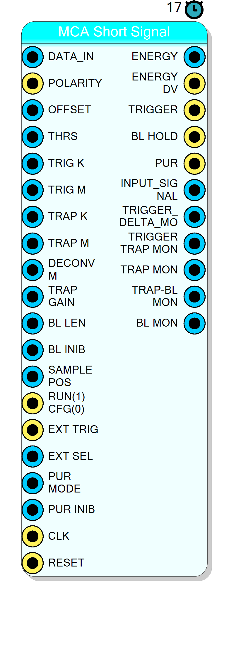
Compact Multi-Channel Analyzer for short signals, optimized for minimal FPGA resource usage. Integrates fast trapezoidal trigger, slow trapezoidal shaper, baseline restorer, and energy sampler with pile-up rejection in a resource-efficient design.
Introduction
The MCA Short Signal block implements a complete digital pulse processing chain optimized for short signals and minimal FPGA area.
This block is ideal for applications where:
- Pulses are short (up to ~512 samples shaping time)
- FPGA resources are limited
- Multiple channels are needed on small FPGAs
- High count rate with short signals is required
The design uses fixed delay line sizes to minimize RAM and logic usage:
- Trigger trapezoidal: 64 samples maximum
- Energy trapezoidal: 512 samples maximum
- Baseline restorer: 512 samples maximum
Unlike the full MCA HLS block which requires runtime HLS compilation, this block uses a pre-compiled VHD IP core that can be directly instantiated without Vitis HLS.
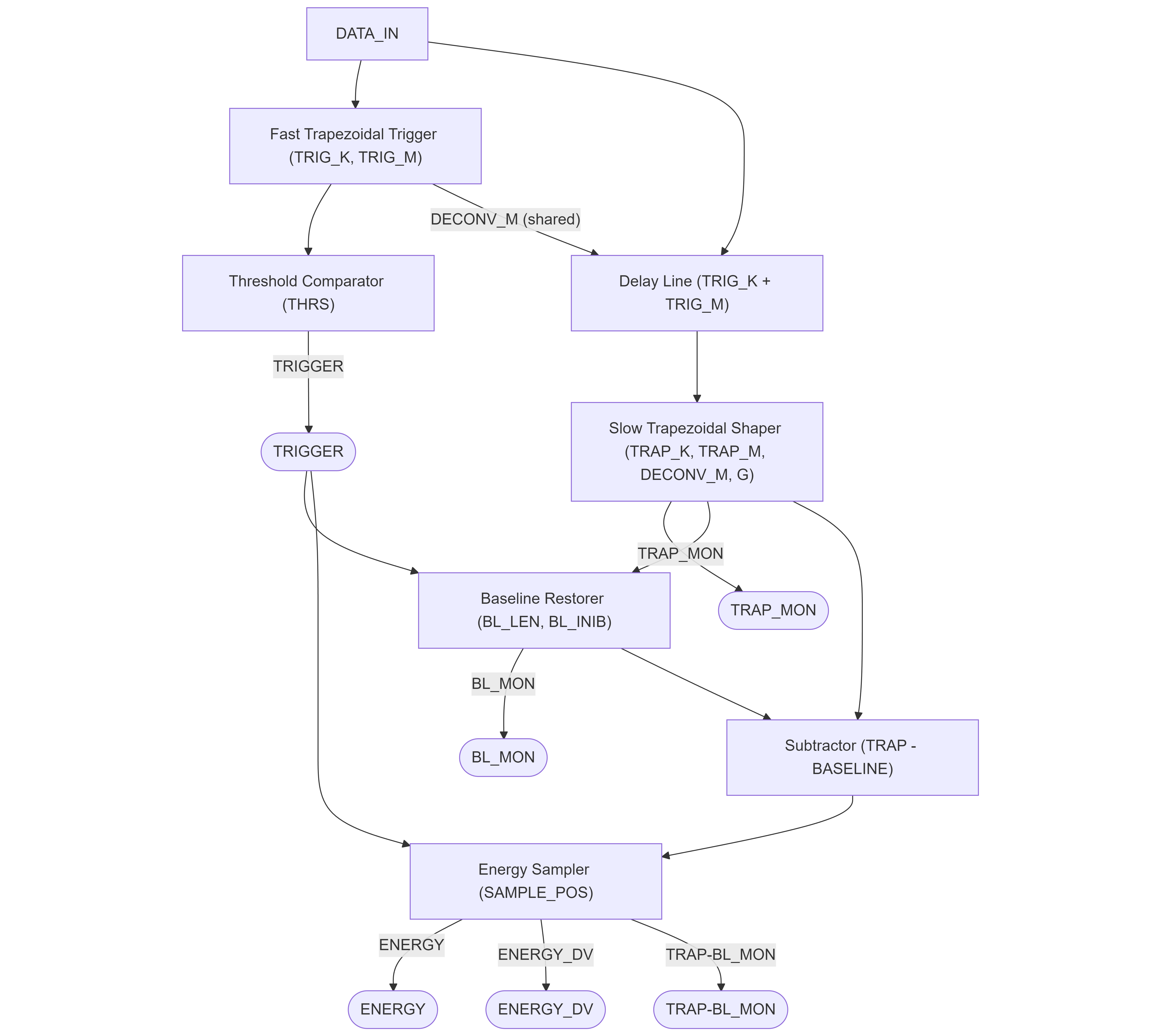
The block combines four processing stages:
- Fast Trapezoidal Trigger: Derivative-based trigger with short shaping times
- Slow Trapezoidal Shaper: Energy measurement with integrated deconvolution
- Baseline Restorer: Moving average with trigger-based hold
- Energy Sampler: Energy extraction with pile-up rejection (PUR)
Pin Description
Signal polarity selection.
- 1: Positive polarity (signal increases on pulse)
- 0: Negative polarity (signal inverted internally)
M = int(256 / (exp(Ts/tau) - 1))
where Ts is sampling period and tau is preamplifier decay time.
Shared between trigger and energy trapezoids.
4-bit pile-up rejection mode selector.
- 0: No PUR - all events accepted
- 1: Simple PUR - reject if trigger during inhibit
- 2+: State machine PUR - wait for clean window
Run/Configure mode control.
- 0: Configuration mode - parameters can be changed, processing reset
- 1: Run mode - active processing
4-bit external trigger mode selector.
- 0: Internal trigger only
- 1: External trigger only
- 2: Internal AND External
- 3: Internal AND NOT External
Properties
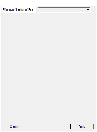
Set the effective number of bits of the ADC board
Effective number of bits of the ADC. Used for polarity inversion calculation when POLARITY=0. Available values: 10, 12, 14, 16, default 14.Default: 14
Options: 10 12 14 16
Usage
Signal Flow Diagram
Resource Optimization
This block is specifically designed to minimize FPGA resource usage:
| Resource | MCA Short Signal | MCA HLS (typical) |
|---|---|---|
| Trigger delay | 64 samples fixed | 128-16384 configurable |
| Energy delay | 512 samples fixed | 128-16384 configurable |
| Baseline delay | 512 samples fixed | 128-16384 configurable |
| HLS required | No | Yes |
| BRAM usage | Low | Medium-High |
When to use this block:
- Scintillator detectors with fast signals (< 4 µs shaping)
- SiPM/PMT readout with short pulses
- Multiple channel systems with limited FPGA resources
- Applications where maximum shaping time is 512 samples
When to use MCA HLS instead:
- HPGe detectors requiring long shaping times (> 512 samples)
- High-resolution spectroscopy needing fine parameter tuning
- Applications requiring timestamps
Processing Stages Detail
Stage 1: Fast Trapezoidal Trigger
The fast trapezoidal filter generates a trigger when a pulse is detected:
- Maximum peaking time: 64 samples (TRIG_K)
- Maximum flat-top: 64 samples (TRIG_M - TRIG_K)
- Derivative-based threshold comparison
The trigger fires when:
- The derivative of the trapezoidal output exceeds THRS
- The derivative then crosses zero (peak detection)
Advantages:
- No baseline calculation required for triggering
- Immune to DC offset and baseline drift
- Very fast response time
Stage 2: Slow Trapezoidal Shaper
Energy measurement filter with integrated deconvolution:
- Maximum peaking time: 512 samples (TRAP_K)
- Maximum flat-top: 512 samples (TRAP_M - TRAP_K)
- Integrated pole-zero cancellation using DECONV_M
- Output scaling with TRAP_GAIN
Trapezoidal Algorithm (Jordanov-Knoll):
$$ d^k[n] = x[n] - x[n-k] $$
$$ d^{k,l}[n] = d^k[n] - d^k[n-l] $$
$$ p[n] = p[n-1] + d^{k,l}[n] $$
$$ r[n] = p[n] + M \cdot d^{k,l}[n] $$
$$ s[n] = s[n-1] + r[n] $$
where:
- $k$ = peaking time (TRAP_K)
- $l$ = k + flat-top (TRAP_M)
- $M$ = deconvolution coefficient (DECONV_M)
Stage 3: Baseline Restorer
Moving average baseline calculation:
$$ \text{baseline}[n] = \frac{1}{2^{\text{BL_LEN}}} \sum_{i=0}^{2^{\text{BL_LEN}}-1} \text{trap}[n-i] $$
- Maximum averaging window: 512 samples
- Baseline is held (frozen) for BL_INIB cycles after each trigger
Stage 4: Energy Sampler with Pile-Up Rejection
Samples energy at the flat-top and provides pile-up rejection (PUR):
$$ \text{energy} = \text{trap}[\text{trigger} + \text{SAMPLE_POS}] - \text{baseline} $$
PUR Modes:
| PUR_MODE | Description |
|---|---|
| 0 | No pile-up rejection - all events accepted |
| 1 | Simple PUR - reject if trigger during inhibit window |
| 2+ | State machine PUR - wait for clean measurement window |
The PUR output indicates when pile-up is detected.
Calculating the Deconvolution Coefficient (DECONV_M)
The deconvolution coefficient removes the exponential decay from preamplifier signals:
$$ M = \frac{256}{e^{T_s / \tau} - 1} $$
where:
- $T_s$ is the sampling period (1 / clock_frequency)
- $\tau$ is the preamplifier decay time constant
- The factor 256 comes from the internal 8-bit fixed-point scaling
Example calculation (Python):
python
import math
clock_freq = 125e6 # 125 MHz
tau = 50e-6 # 50 µs preamplifier decay time
Ts = 1.0 / clock_freq # 8 ns
M = int(256 / (math.exp(Ts / tau) - 1))
# Result: M = 1599744 (0x186A00)
External Trigger Modes
The EXT_SEL input controls trigger source:
| EXT_SEL | Trigger Source |
|---|---|
| 0 | Internal trigger only |
| 1 | External trigger only (EXT_TRIG) |
| 2 | Internal AND External (coincidence) |
| 3 | Internal AND NOT External (anti-coincidence) |
Saturation Protection
The block includes automatic saturation detection:
- When input reaches 0xFFFF, processing is temporarily disabled
- This prevents false triggers and energy measurements during saturation
- Processing resumes automatically when saturation clears
Timing and Latency
- Total processing latency: 17 clock cycles
- Throughput: 1 sample per clock cycle (II=1)
- Trigger to energy delay: Configurable via SAMPLE_POS
Typical Applications
- Scintillator detectors (NaI, CsI, LaBr3, LYSO)
- SiPM and PMT readout
- Portable radiation monitors
- Multi-channel gamma cameras
- Resource-constrained FPGA designs