
Constant Bit (True/False) [TM]
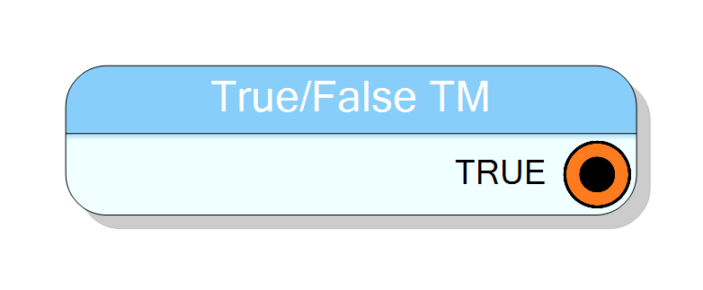
Time-multiplexed constant single-bit source. Generates boolean True (1) or False (0) values across multiple TM phases (1-32). Provides logic high/low patterns for TM control signals, enable flags, or polarity settings. Can provide same value for all phases or different values per phase. Zero latency.
Introduction
This block generates constant single-bit boolean values for time-multiplexed (TM) data streams. It produces fixed True/False patterns across multiple TM phases, with each phase receiving its own configurable boolean constant.
The component supports two operating modes:
- Same value for all phases: One boolean constant replicated across all TM phases
- Different values per phase: Unique True/False value for each TM phase
The TM Factor property (1-32) determines how many parallel boolean values are generated per clock cycle.
The output is purely combinational with zero clock latency, suitable for direct use as TM enable signals, control flags, or polarity settings in TM processing pipelines.
Pin Description
Constant bit-vector output, always TM (time-multiplexed).
Width: TM Factor bits (1 bit per phase).
Each bit represents the boolean state (True=1, False=0) for the corresponding TM phase. The output is combinational (zero latency) and available immediately after FPGA configuration.
Bit assignment: Bit 0 = Phase 0, Bit (N-1) = Phase (N-1).
During synthesis, constant bits are typically tied directly to VDD (1) or GND (0), consuming zero FPGA resources.
Properties
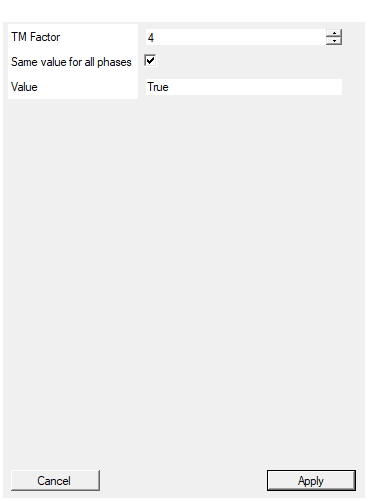
Time Multiplexing factor (number of phases)
Time-multiplexing factor (number of parallel phases). Allowed values: 1 to 32. Determines how many boolean constant values are generated per clock cycle (one bit per phase). Must match downstream TM components.Default: 4
Range: 1 – 32
If true, the same constant value is used for all TM phases. If false, specify different values for each phase separated by comma, semicolon or space (e.g., True,False,True,False)
If True, use a single boolean Value for all TM phases (replicated). If False, provide exactly TMFactor comma/semicolon/space-separated boolean values (one per phase). Mismatch causes compilation error.Default: True
Set the value of the constant. If ‘Same for all phases’ is true: Use single value (True or False) If ‘Same for all phases’ is false: Use comma/semicolon/space separated values (e.g., True,False,True,False)
Boolean constant value(s). Accepts: True, False, 1, or 0 (case-insensitive). If SameForAllPhases=True: single value (e.g., True). If SameForAllPhases=False: TMFactor values separated by comma, semicolon, or space (e.g., True,False,True,False for TM=4). Each value is converted to 1 (True) or 0 (False).Default: True
Functional description
The component implements a time-multiplexed constant boolean source in VHDL. For TM Factor = $N$, the output contains $N$ single-bit values:
$$ \mathrm{OUT}(t) = [b_0, b_1, b_2, \ldots, b_{N-1}] $$
where each $b_i \in {0, 1}$ represents False (0) or True (1).
TM Factor and phase assignment
The TM Factor determines the number of parallel boolean phases:
| TM Factor | Phases per Clock | Total Output Width |
|---|---|---|
| 2 | 2 | 2 bits |
| 4 | 4 | 4 bits |
| 8 | 8 | 8 bits |
| 16 | 16 | 16 bits |
| 32 | 32 | 32 bits |
Each phase occupies a single bit in the output bus:
- Phase 0: bit
[0] - Phase 1: bit
[1] - Phase N-1: bit
[N-1]
Operating modes
Mode 1: Same value for all phases
When SameForAllPhases = True, a single boolean value is replicated:
Value: True
TM Factor: 4
Output (4 bits): [1, 1, 1, 1] = "1111"
Phase0 Phase1 Phase2 Phase3
Value: False
TM Factor: 4
Output (4 bits): [0, 0, 0, 0] = "0000"
Phase0 Phase1 Phase2 Phase3
Mode 2: Different values per phase
When SameForAllPhases = False, provide comma/semicolon/space-separated values:
Value: True, False, True, False
TM Factor: 4
Output (4 bits): [1, 0, 1, 0] = "1010"
Phase0 Phase1 Phase2 Phase3
Important: The number of values must exactly match the TM Factor, or a compilation error will occur.
Value formats
Each phase value accepts multiple boolean representations:
- True:
True,true,TRUE,1 - False:
False,false,FALSE,0
Examples of valid multi-value specifications:
Value: True, False, True, True
Value: 1, 0, 1, 1
Value: true, false, true, false
Mixed formats are allowed:
Value: True, 0, false, 1
Binary pattern generation
The output is a compact bit-vector where each bit represents one TM phase. This is useful for creating:
- Alternating patterns:
True,False,True,False→ “1010” - Gating patterns:
True,True,False,False→ “1100” - Sparse enables:
True,False,False,False→ “1000” - All-enabled:
True(replicated) → “1111…1” - All-disabled:
False(replicated) → “0000…0”
Implementation details
The VHDL implementation concatenates all phase bits into a single bus:
vhdl
signal CONST : STD_LOGIC_VECTOR(TMFactor-1 downto 0);
CONST <= "b(N-1)" & "b(N-2)" & ... & "b(1)" & "b(0)";
where each b(i) is ‘1’ (True) or ‘0’ (False).
During synthesis, constant bit sources are typically optimized away, with the output net tied directly to VDD (for ‘1’) or GND (for ‘0’).
Timing
The component is purely combinational with zero latency:
| Property | Latency (clock cycles) |
|---|---|
| Constant Bit [TM] | 0 |
All TM phases are available immediately (no pipeline delay).
Typical use cases
- TM enable signals: Control which TM phases are active (e.g., enable phases 0-3, disable 4-7)
- TM polarity control: Set per-phase inversion or active-high/low behavior
- TM gating patterns: Define which phases should propagate data
- TM mode selection: Choose between two operating modes per TM phase
- TM test patterns: Generate known boolean sequences for TM pipeline verification
- TM masking: Create bit masks for selective TM phase processing
- TM channel enables: Enable/disable individual channels in multi-channel TM systems
Example configurations
Example 1: All phases enabled (TM=8)
Value: True
TMFactor: 8
SameForAllPhases: True
Output (8 bits): "11111111"
Use case: Enable all TM phases for processing
Example 2: Alternating pattern (TM=8)
Value: True, False, True, False, True, False, True, False
TMFactor: 8
SameForAllPhases: False
Output (8 bits): "10101010"
Use case: Alternating enable/disable for interleaved processing
Example 3: First half enabled (TM=4)
Value: True, True, False, False
TMFactor: 4
SameForAllPhases: False
Output (4 bits): "1100"
Use case: Process only the first two TM phases
Example 4: Sparse enable (TM=16)
Value: True, 0, 0, 0, True, 0, 0, 0, True, 0, 0, 0, True, 0, 0, 0
TMFactor: 16
SameForAllPhases: False
Output (16 bits): "1000100010001000"
Use case: Enable every 4th phase for downsampling
Example 5: All phases disabled (TM=32)
Value: False
TMFactor: 32
SameForAllPhases: True
Output (32 bits): "00000000000000000000000000000000"
Use case: Disable all TM phases (e.g., for power saving or testing)
Design recommendations
Pattern design
- Uniform patterns (all True/False): Use SameForAllPhases = True for simplicity
- Alternating patterns: Useful for interleaving or phase-staggered processing
- Sparse patterns: Enable only specific phases for selective processing
- Grouped patterns: Enable contiguous blocks of phases for segmented processing
Resource usage
The component consumes zero FPGA resources after synthesis optimization, as constant bits are hardwired to power/ground rails.
Debugging tips
When designing complex TM systems, use different boolean patterns per phase to help identify which phase is active during simulation or hardware debugging.