
Oscilloscope TM
The Oscilloscope TM is a waveform digitizer designed for time-multiplexed (TM) signals, allowing the acquisition of multiple samples per clock cycle. The component is designed to acquire both analog and digital signals, for firmware debugging and signal analysis.
Introduction
The Oscilloscope TM is a sophisticated digital waveform digitizer that operates on time-multiplexed signals. In a single clock cycle, the board captures multiple samples, significantly enhancing data acquisition efficiency.
The Time-Multiplexed (TM) Oscilloscope block extends the classic scope to handle high-speed, parallel sample streams from fast front-end boards by packing TM_FACTOR samples for each of n channels into a single wide TM * nBit word per clock. On every rising edge of CLK, the entire A_x word is latched, internally demultiplexed into time-ordered analog (A) and digital (D0–D3) samples, and buffered in per-channel FIFOs. The standard Oscilloscope GUI then reads these FIFOs exactly as if it had acquired one sample at a time—allowing you to configure trigger source, mode, edge, level, time-base and pre-trigger settings just like a conventional scope.
The operation of the Oscilloscope TM can be mathematically described by considering the time-multiplexing factor, $( TM FACTOR )$, which represents the number of samples captured per clock cycle. The total number of samples, $( N )$, captured over a period $( T )$ is given by: $$ [ N = M \times f_{\text{clk}} \times T ] $$ where $f_{\text{clk}}$ is the clock frequency.
The component supports both analog and digital inputs, with configurable decimation and trigger settings, allowing precise control over data acquisition parameters. The decimation factor, $( D )$, reduces the data rate by selecting one sample every $( D )$ samples, effectively lowering the bandwidth and storage requirements.
graph TD
subgraph ADC ["ADC (Time-Multiplexed Output)"]
A1["Sample[0]"]
A2["Sample[1]"]
A3["Sample[2]"]
A4["Sample[3]"]
end
subgraph Memory ["Memory (Sequential Write)"]
M1["Address N<br/>← Sample[0]"]
M2["Address N+1<br/>← Sample[1]"]
M3["Address N+2<br/>← Sample[2]"]
M4["Address N+3<br/>← Sample[3]"]
end
A1 --> M1
A2 --> M2
A3 --> M3
A4 --> M4
Pin Description
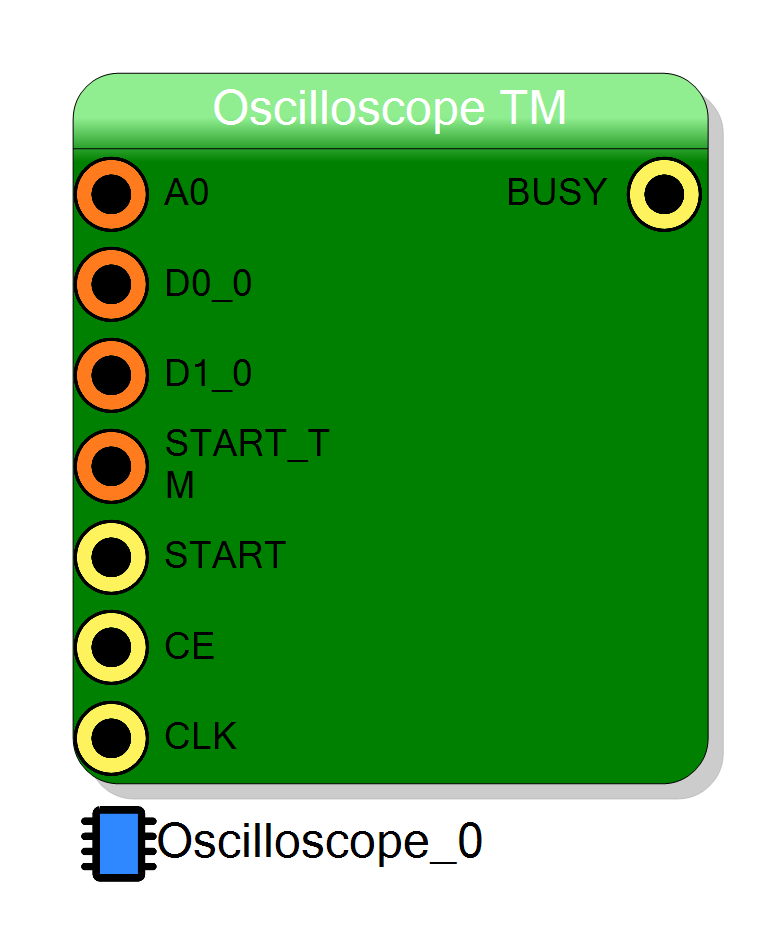
A_0 pin is an input for the first analog channel. It accepts a time-multiplexed signal only, capturing TM_FACTOR samples per clock cycle.
D0_0 pin is a digital input channel. It captures single-bit digital signals in a time-multiplexed format, allowing for the acquisition of multiple digital states per clock cycle.
D0_0, the D1_0 pin serves as an additional digital input channel, supporting time-multiplexed signal acquisition.
START_TM pin is used to initiate the time-multiplexed acquisition process. A high signal on this pin triggers the start of data capture across all channels.
In respect to the START pin, this pin is used to start the acquisition process in time-multiplexed mode, allowing indicating which is the first sample of the acquisition.
START pin functions as a standard trigger input, initiating the acquisition sequence when a rising edge is detected.
CE (Clock Enable) pin controls the clock gating for the acquisition process. When high, the clock signals are enabled, allowing data capture.
CLK pin provides the clock signal necessary for synchronizing the acquisition process.
Properties
Set the name of the endpoint
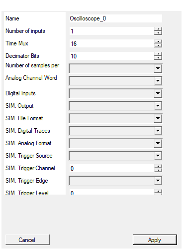
This property sets the name of the endpoint for identification purposes within the system. This must be unique across all components in the design.Default: Oscilloscope_0
Set the number of input to the virtual block
Defines the number of input channels available for data acquisition. This property allows for scalability in the number of signals that can be monitored simultaneously.Default: 1
Range: 1 – 32
Set number of samples for each clock cycle
Specifies the time-multiplexing factor, determining how many samples are captured per clock cycle. Depending on the TM_FACTOR of the DAQ boardDefault: 16
Range: 1 – 16
Set number of bits for the decimator (max decimation = 2**DecimatorBits)
Sets the number of bits used for the decimator configuration. The decimation factor maximum limit Depending by this property. Decimator allows to select a sample every ( 2^{\text{DecimatorBits}} ) samples.Default: 10
Range: 1 – 10
Set the number of samples stored for each acquisition
Determines the number of samples stored for each acquisition channel. This property affects the memory usage by the captured waveform.Default: 1024
Options: 128 256 512 1024 2048 4096 8192 16384
Set the analog channel word size in bits
Configures the word size for analog channels, defining the bit-width of each sample.Default: 16
Options: 16 32 64
Enable/Disable Digital Inputs
Enables or disables the digital inputs. When enabled, digital signals are captured and processed alongside analog inputs,Default: Enabled
Options: Enabled Disabled
What the block writes to disk WHEN THE PROJECT IS SIMULATED (no effect on the synthesized design). None: the block does nothing, as it has always done. Single file: every captured waveform goes into one file. Multi file per channel: one file per analog channel (and its digital lines). Multi file per event: one file per trigger. The samples are written UNROLLED: the time-multiplexed words of each clock come out one after the other, phase 0 first, so the file is a plain sample stream. The files are written in the sim_results folder of the project, named after
What the block writes to disk when the project is simulated. It has no effect on the synthesized design.
| Value | Effect |
|---|---|
| None | Nothing is written (default). |
| Single file | Every captured waveform goes into one file. |
| Multi file per channel | One file per analog channel, with its digital lines. |
| Multi file per event | One file per trigger. |
Samples are written unrolled: the time-multiplexed words of each clock come out
one after the other, phase 0 first, so the file is a plain sample stream —
T0.phase0 T0.phase1 … T0.phaseN-1 T1.phase0 …
Files go to the project’s sim_results folder, named after <page>_<endpoint> plus
_ch<n> / _ev<n>. The exact paths are printed in the compiler log.
Default: None
Default: None
Options: None Single file Multi file per channel Multi file per event
Layout of the simulation output files. The first column is always the timestamp, in ns, of the trigger that captured the waveform. One sample per row: ‘<time_ns>
Layout of the simulation output files. The first column is always the timestamp, in ns, of the trigger that captured the waveform.
- One sample per row —
<time_ns> <A0> <A1> … <D0_0> <D1_0> …: one row per unrolled sample, one column per analog channel and per digital trace. - One waveform per row —
<time_ns> <trace> <s0> … <sN-1>: the whole unrolled waveform of one trace on a single row.
Default: One sample per row
Default: One sample per row
Options: One sample per row One waveform per row
Whether the 2 digital lines of each channel are written to the simulation files alongside the analog trace. Disable it to get analog-only files, which are much smaller and easier to plot. It has no effect when the block’s Digital Inputs are disabled: there is nothing to write.
Whether the 2 digital lines of each channel are written to the simulation files alongside the analog trace. No effect when DigitalIn is Disabled. Default: EnabledDefault: Enabled
Options: Enabled Disabled
How an analog sample is interpreted, both when it is written to the file and when it is compared against the simulation trigger level. Unsigned reproduces the hardware exactly (the real block compares the raw word as unsigned). Choose Signed when the input carries two’s complement data and you want a plottable trace. An unsigned 32 bit sample has no VHDL integer representation and is written as signed.
How an analog sample is interpreted, both when written to the file and when compared against the simulation trigger level. Unsigned matches the hardware, which compares the raw word as unsigned; pick Signed for two’s complement inputs. Default: UnsignedDefault: Unsigned
Options: Unsigned Signed
Trigger source used during the simulation. It replaces CONFIG_TRIGGER_MODE. External: the START / START_TM pins. Analog threshold: the level crossing on the selected channel, evaluated on the unrolled sample stream. Free run: capture continuously. Digital D0/D1: the selected digital line of the selected channel. The scope arms itself at reset and re-arms after every capture, since no software can arm it in a simulation.
Trigger source used during the simulation; it replaces CONFIG_TRIGGER_MODE.
Options: External (START / START_TM), Analog threshold, Free run,
Digital D0, Digital D1.
The scope arms itself at reset and re-arms after every capture, because no software
can write CONFIG_ARM in a simulation.
Default: Analog threshold
Default: Analog threshold
Options: External (START / START_TM) Analog threshold Free run Digital D0 Digital D1
Channel the simulation trigger looks at. Used by the analog threshold and by the digital D0/D1 sources; ignored by the others. Clamped to the number of inputs at compile time.
Channel the simulation trigger looks at. Used by the analog threshold and by the digital sources. Clamped to the number of inputs at compile time, with a warning. Default: 0Default: 0
Range: 0 – 31
Edge of the analog threshold trigger. Rising fires when the sample crosses the level upwards, Falling when it crosses it downwards. Ignored by the other trigger sources.
Edge of the analog threshold trigger: Rising or Falling. The crossing is evaluated on the unrolled sample stream, so it is detected between two consecutive phases of the same clock as well as across a packet boundary. Default: RisingDefault: Rising
Options: Rising Falling
Threshold of the analog trigger, in raw ADC counts, read with the SIM. Analog Format interpretation. It replaces CONFIG_TRIGGER_LEVEL.
Threshold of the analog trigger in raw ADC counts, read with the SIM. Analog Format interpretation. ReplacesCONFIG_TRIGGER_LEVEL.
Default: 0
Default: 0
Number of samples kept before the trigger, counted in UNROLLED samples - i.e. in rows of the output file, not in time-multiplexed packets like the CONFIG_PRETRIGGER register does. Must be smaller than the number of samples per channel; it is clamped at compile time.
Number of samples kept before the trigger, counted in unrolled samples — that is, in rows of the output file, not in time-multiplexed packets the way theCONFIG_PRETRIGGER register counts them. Clamped at compile time.
Default: 0
Default: 0
Decimation used during the simulation, applied to the UNROLLED sample stream: 0 keeps every sample, 1 keeps one out of two, N keeps one out of N+1. As in hardware, a trigger that falls on a discarded sample is lost.
Decimation applied to the unrolled sample stream: 0 keeps every sample, 1 keeps one out of two, N keeps one out of N+1. As in hardware, a trigger falling on a discarded sample is lost. Default: 0Default: 0
Stop capturing after this many waveforms. The scope free-runs in simulation, so this is what keeps a long run from producing a huge file - or, in ‘Multi file per event’ mode, a huge number of files. 0 means no limit.
Stop capturing after this many waveforms. The scope free-runs in simulation, so this is what keeps a long run from producing a huge file — or, in Multi file per event mode, a huge number of files. 0 means no limit. Default: 64Default: 64
Oscilloscope Configuration Registers
CONFIG_ARM
- A rising edge (0 → 1) on this register enables the oscilloscope acquisition.
- It acts as a trigger arm: write
0, then1to activate.
CONFIG_DECIMATOR
- Sets the decimation factor for the output data.
- A value of
0disables decimation; higher values reduce the sampling rate accordingly.
CONFIG_TRIGGER_MODE
- Defines the trigger mode and its associated parameters:
| Bits | Purpose | Description |
|---|---|---|
| 0–2 | Trigger Source | 000 → External trigger001 → Analog signal010 → Software trigger100 to 111 → Digital inputs 0–3 |
| 3 | Trigger Edge (Analog mode only) | 0 → Rising edge1 → Falling edge |
| 6 | Software Trigger | Set to 1 to trigger immediately when in software mode |
| 8–15 | Channel Selection (Analog/Digital modes) | Selects which channel to monitor |
CONFIG_PRETRIGGER
- Sets the number of pre-trigger samples, i.e., how far back in time the waveform capture should begin relative to the trigger event.
CONFIG_TRIGGER_LEVEL
- Specifies the trigger threshold level (in LSB) used for analog signal triggering.
READ_STATUS
-
Indicates data availability:
0→ Data not ready1→ Data available for reading
READ_POSITION
- Provides the sample index of the trigger within the captured data buffer.
Reading Waveform Data
Once data is ready (READ_STATUS = 1), waveform samples can be retrieved by reading from the oscilloscope’s data address (defined in the JSON descriptor). The number of samples is equal to the configured nsamples.
🌀 Data Reordering and Circular Buffer Handling
After acquisition, data must be reordered so the trigger event always appears at the same position in the waveform, defined by CONFIG_PRETRIGGER.
Two scenarios are possible:
1. Trigger after the pre-trigger index
-
fix_position > 0 -
Reconstruct data as:
reordered_data = data[fix_position : ] + data[ : fix_position]
2. Trigger before the pre-trigger index (wrap-around)
-
fix_position < 0 -
Use circular indexing:
idx = fix_position + nsamples reordered_data = data[idx : ] + data[ : idx]
This ensures consistent waveform alignment for analysis and visualization.
Simulation Output
In the synthesized design the captured window is read back over the register bus by
software, which also arms the scope and configures the trigger. During a project
simulation none of that happens, so the block can instead run itself and dump the
waveforms it captures into the project’s sim_results folder.
Unrolled samples
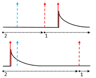
The block receives TimeMultiplexing samples per clock. The simulation output expands
them back into a plain sample stream, phase 0 first — phase 0 is the LSB slice of the
ANALOG bus and it is the oldest sample of the packet:
T0.phase0 T0.phase1 T0.phase2 T0.phase3 T1.phase0 T1.phase1 ...
So one row (or one column, in waveform per row layout) is one sample, and consecutive rows are consecutive in time regardless of the TM factor. SIM. Pre-trigger and SIM. Decimator are likewise expressed in unrolled samples, so they mean the same thing as the row index in the file.
What is and is not reproduced
Unlike the scalar Oscilloscope — whose simulation model is the real control_process
with the registers swapped for properties — this is a behavioural model. The hardware
capture path packs decimated words through the strobe_generator so that one BRAM word
is filled per clock; that machinery exists only to make the memory dense, and there is no
readback port here to observe it. What is reproduced is the observable result: which
samples end up in the window, in which order, around which trigger.
Also worth knowing:
BUSY,READ_STATUSandREAD_POSITIONbecome live as soon as the capture is enabled. With SIM. Output = None they stay at 0, exactly as they always did.- Files are closed after every waveform, so the data on disk is complete even if the simulation is stopped in the middle of the run.
- An unwritable path degrades to one warning and disables the capture; it never kills the simulation.